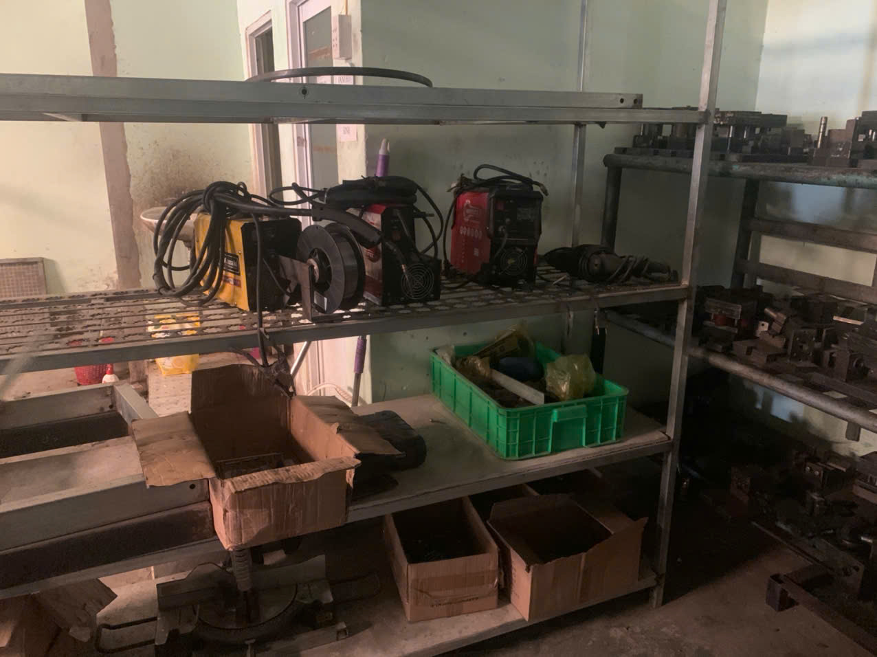

I once lost a full production run because a supplier welded stainless steel brackets to galvanized steel panels—every single joint failed within weeks.
Welding compatibility and material matching for stamping parts requires pairing metals with similar metallurgical properties, controlling surface coatings like zinc plating below 8–12 microns, designing proper projection geometry, and selecting the correct welding method to prevent weld expulsion, cracking, and joint failure in finished assemblies.
This article walks through the core rules, the traps to avoid, and the process controls that separate a reliable stamped-and-welded assembly 1 from a costly failure. Whether you source custom brackets, clips, or mounting hardware from Asia, this guide will help you ask the right questions before production starts.
How can I ensure my stamping supplier matches base metals correctly for welding compatibility?
A lesson we learned early at DEWIN came from a U.S. client who sent drawings specifying low-carbon steel for one bracket and stainless steel for the mating part—nobody flagged the mismatch until weld trials failed spectacularly carbon equivalent 2.
To ensure correct base metal matching, request material test reports for every stamped component, confirm that both parts share compatible alloy families, and verify that your supplier's weld procedure specification explicitly names the approved material pairings for each joint in the assembly.

Why Base Metal Properties Matter
The single biggest cause of weld failure in stamped assemblies is material mismatch. When two metals have different melting points, different thermal expansion coefficients 3, or incompatible chemistries, the weld nugget cannot form properly. The result is spatter, porosity, or a brittle joint that cracks under load.
Low-carbon steel welds well to low-carbon steel. Stainless steel welds well to stainless steel. But stainless steel welded to galvanized steel is a recipe for disaster. The zinc coating on galvanized steel vaporizes at a lower temperature than the stainless melts. This causes weld expulsion and inconsistent nugget formation. The joint looks fine on the surface but has almost no structural strength.
The Compatibility Matrix
Here is a practical reference table we share with our clients during the co-development phase:
| Base Metal A | Base Metal B | Compatible? | Notes |
|---|---|---|---|
| Low-carbon steel | Low-carbon steel | ✅ Yes | Ideal pairing; standard resistance or MIG/TIG methods work well |
| Stainless steel | Stainless steel | ✅ Yes | Match filler metal to the specific grade (304, 316, etc.) |
| Stainless steel | Galvanized steel | ❌ No | Zinc causes expulsion, poor nugget, and galvanic corrosion 4 risk |
| Aluminum | Aluminum | ✅ Yes | Requires oxide removal and precise heat input control |
| Aluminum | Stainless steel | ⚠️ Conditional | Needs specialized filler and laser or friction methods; risk of intermetallic compounds |
| Copper | Stainless steel | ⚠️ Conditional | Nickel-based filler acts as diffusion barrier; brittle phases possible |
| HSLA steel | HSLA steel | ✅ Yes | Compatible but may need adjusted weld schedules |
| AHSS | AHSS | ⚠️ Conditional | Preheating often required; sub-critical HAZ softening is a concern |
Carbon Equivalent: The Hidden Filter
Beyond the alloy name, I always tell our engineering team to check the carbon equivalent 5 (CE) of the steel. Parts with a CE above 0.40% are prone to forming brittle martensite in the heat-affected zone 6. This leads to hydrogen-induced cracking, especially in thicker gauges. When we audit suppliers in Vietnam or elsewhere in Asia, we ask for the CE value on the mill certificate. If it is too high, we specify preheating or switch to a lower-carbon grade before tooling even begins.
Filler Metal Selection
Filler metal selection is another area where mistakes happen. The filler should match the base metal's yield strength 7, not just its tensile strength. This matters most in fatigue-prone applications—mounting brackets for automotive or industrial equipment, for example. If the filler is too strong, the heat-affected zone becomes the weak link. If the filler is too weak, the weld itself fails first. Our approach is to lock down the filler specification in the weld procedure before any samples are made.
What material certifications should I request to avoid welding defects in custom stamped parts?
During a recent project for a U.S. distributor, we caught a critical issue only because we demanded full mill certificates up front—the supplier's incoming steel had a sulfur content high enough to cause hot cracking in every weld.
Request mill test reports (EN 10204 3.1 or equivalent) showing chemical composition, mechanical properties, and surface coating thickness for every lot of raw material; additionally, require a weld procedure qualification record (WPQR) and evidence of operator certification to prevent welding defects in custom stamped parts.
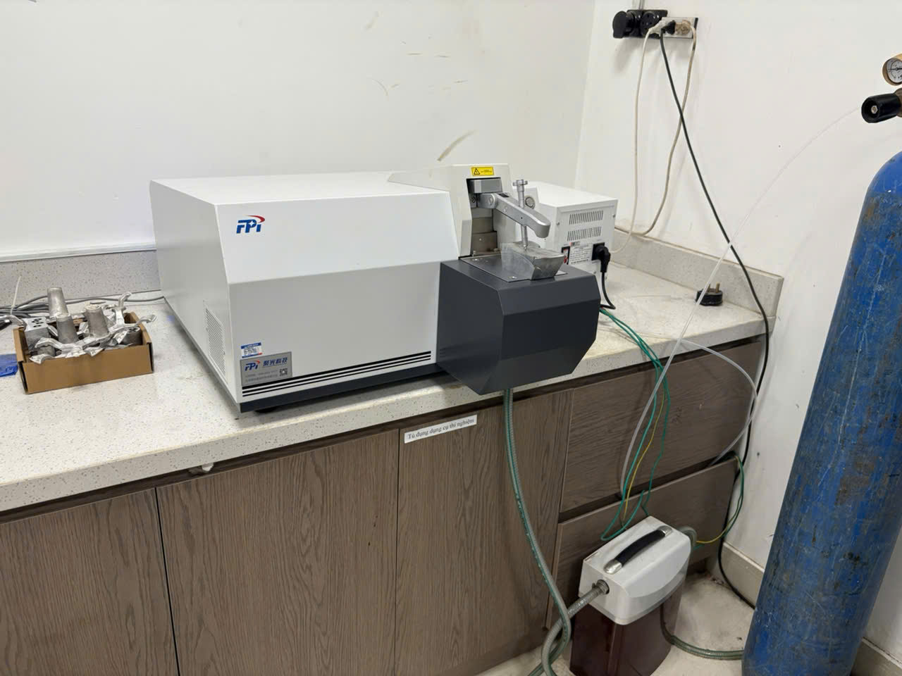
The Certification Checklist
Not all certifications carry the same weight. Here is a breakdown of what to ask for and why each document matters:
| Document | What It Proves | Why It Matters for Welding |
|---|---|---|
| Mill Test Report (MTR / 3.1 cert) | Chemical composition, yield/tensile strength, elongation | Confirms CE value, sulfur/phosphorus limits, and alloy grade accuracy |
| Coating Thickness Report | Zinc or other plating thickness in microns | Zinc above 8–12 microns causes weld expulsion and spatter |
| Weld Procedure Specification (WPS) | Approved welding parameters for each joint | Ensures current, voltage, and sequence match the material pair |
| WPQR (Procedure Qualification Record) | Weld procedure has been tested and passed | Proves the method works on the actual material, not just in theory |
| Welder Qualification Certificate | Operator is trained and tested | Reduces variability from human skill differences |
| PPAP (Production Part Approval Process) | Full process capability demonstrated | Covers dimensional, material, and process validation in one package |
Lurking Contaminants: Lubricants and Residues
One area that rarely appears on a purchase order is the stamping lubricant. Specialized stamping lubricants containing sulfur or chlorine compounds can leave residues on the part surface. When these residues reach welding temperatures, they vaporize and get trapped in the weld pool. The result is sub-surface porosity or "hot shortness"—a condition where the weld bead cracks while still cooling.
Our standard practice is to specify a post-stamping cleaning step before any welding operation. We also ask suppliers to disclose the lubricant brand and type so our quality team can assess the risk. This is a small step that prevents large problems.
The Plating Trap: The 12-Micron Rule
Zinc plating is one of the most common surface treatments for stamped steel parts. It provides corrosion resistance 8 at a low cost. But when that plating is thicker than 8–12 microns, it becomes a serious obstacle to welding. The zinc melts and boils before the steel underneath reaches welding temperature. This causes violent expulsion, inconsistent weld nuggets, and spatter that contaminates the electrode tips.
The gold standard is a weld-before-plate sequence. We stamp the parts, weld the assembly, then send it for plating. If logistics require plating first, we insist on masking the weld zone to keep it bare. This adds a step, but it eliminates the single most common source of weld quality complaints we see in imported stamped assemblies.
Cold-Work Annealing Risk
Stamping cold-works the metal. It hardens the grain structure, especially at bend lines and drawn features. When welding heat reaches these areas, it can locally anneal the hardened structure. The result is a softened heat-affected zone that may fail at loads well below the original stamped material's rating. Requesting mechanical property data on both the raw material and the as-stamped condition helps quantify this risk. For high-strength applications, we sometimes recommend post-weld heat treatment or design changes that move the weld away from heavily cold-worked zones.
Why do dissimilar metal combinations cause weld failures in my stamping projects?
A trade-off we weigh on nearly every multi-component stamping project is cost versus metallurgical compatibility—using a cheaper alloy for one part and a premium alloy for another seems efficient until the weld between them falls apart.
Dissimilar metal combinations cause weld failures because differences in melting points, thermal expansion coefficients, and electrochemical potential create brittle intermetallic compounds, residual stress cracking, and accelerated galvanic corrosion at the joint interface, all of which compromise structural integrity.
The Science Behind Dissimilar Metal Failures
When two different metals are melted together, their atoms mix in the weld pool. If the metals have very different crystal structures or atomic sizes, they form intermetallic compounds instead of a solid solution. Intermetallic compounds are extremely hard and brittle. They cannot absorb stress. A joint filled with intermetallic phases will crack under vibration, thermal cycling, or even simple handling.
Aluminum welded to stainless steel is a classic example. The iron-aluminum intermetallic layer that forms is so brittle that even a thin band of it can cause the joint to shatter. To manage this, specialized filler alloys—often nickel-based—are used as a diffusion barrier. Laser welding with very short exposure times can also limit intermetallic growth. But these are expensive solutions that add complexity.
Thermal Expansion Mismatch
Even if two metals can form a decent weld, they may still fail in service if their thermal expansion coefficients differ significantly. As the assembly heats up and cools down—during operation, shipping, or even daily temperature swings—one metal expands more than the other. This puts the weld under cyclic stress. Over time, fatigue cracks develop at the fusion line.
For stamped mounting brackets and clips like the ones we produce, this is especially relevant in automotive and outdoor applications where temperature ranges are wide.
Galvanic Corrosion at the Joint
Weldability of dissimilar metals is not just about the weld itself. After welding, the two metals sitting in contact create a galvanic cell. If moisture or any electrolyte is present, the more active metal corrodes preferentially. This galvanic corrosion concentrates at the weld interface—the exact location where you need the most strength.
I always advise our clients to check the galvanic series before finalizing a design that pairs different metals. If the electrochemical potential difference is large, we recommend either switching to matched metals or adding a barrier coating after welding.
Residual Stress and Delayed Cracking
Stamping introduces residual stresses into the part. Welding adds more residual stress through thermal contraction. When dissimilar metals are involved, these stresses compound because the two materials cool and contract at different rates. The result can be delayed cracking—cracks that appear hours or even days after welding, long after the parts have passed initial inspection.
For high-precision stamped components, post-weld stress-relief treatments are sometimes the only reliable solution. But they add cost and lead time, so the smarter approach is to avoid the dissimilar pairing in the first place when possible. Understanding how stainless steel, aluminum alloy, and carbon steel compare in sheet metal fabrication can help you make better material choices early in the design process.
Springback and Fit-Up Stress
Stamped parts have inherent springback. When two dissimilar stamped parts are forced into alignment for welding, the clamping introduces fit-up stress. This stress gets locked into the joint after welding. Combined with the metallurgical challenges of dissimilar metals, fit-up stress can reduce the fatigue life of the joint by 30–50% compared to a stress-free assembly. Joint design optimization—including proper tolerancing and flexible fixturing—helps reduce this hidden risk.
How do I verify a supplier's welding process controls before starting production?
One interaction that shaped how we run supplier audits at DEWIN happened when a client's bracket assembly passed all dimensional checks but failed catastrophically in the field—the root cause was a welding operator who had changed the current setting without authorization.
Verify a supplier's welding process controls by auditing their weld procedure specifications, reviewing operator qualification records, inspecting electrode maintenance logs, confirming destructive and non-destructive test frequencies, and requiring a PPAP submission that includes weld cross-section samples and process capability data before approving production.

What to Look for During a Supplier Audit
When our team visits a supplier—whether in Vietnam, Taiwan, or elsewhere—we follow a structured checklist. The goal is not just to see clean floors and organized workstations. We want evidence that the welding process is controlled, repeatable, and documented.
Here are the key areas we evaluate:
- Weld Procedure Specification (WPS): Is there a written procedure for every joint type? Does it specify current, voltage, electrode force, weld time, and squeeze time?
- Operator Qualification: Are welders tested and certified for the specific process (resistance, MIG, TIG, laser)? Are records current?
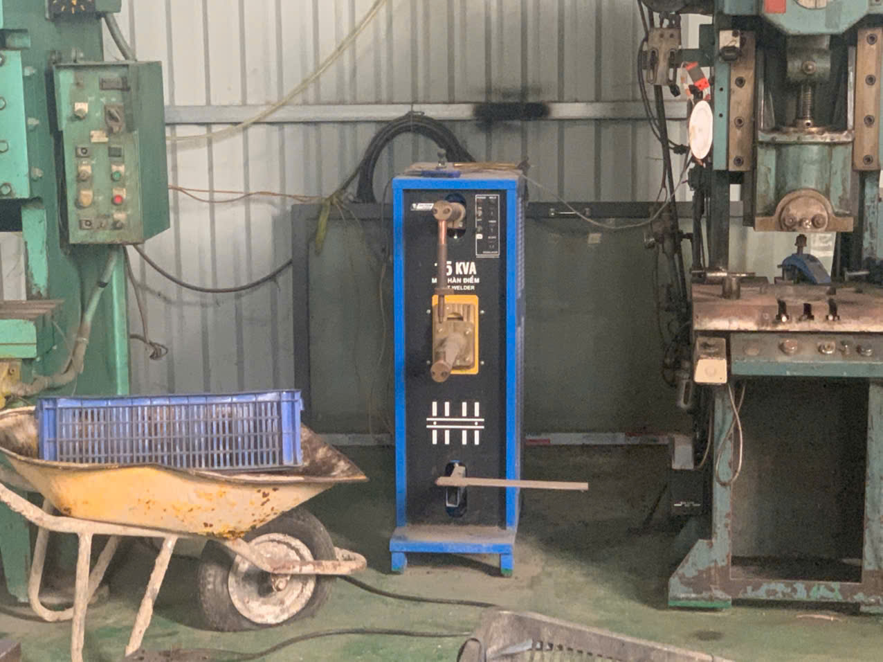
- Electrode Maintenance: For resistance spot welding 9 and projection welding, electrode tip condition directly affects weld quality. We look for a documented tip-dressing schedule and replacement criteria.
- Destructive Testing: Does the supplier perform regular peel tests or cross-section macro-etch tests? At what frequency?
- Non-Destructive Testing: For critical joints, ultrasonic or X-ray inspection may be required. We confirm equipment calibration and operator training.
- Parameter Lock-Down: Can operators change weld settings without supervisor approval? The best suppliers use password-protected weld controllers.
Process Control Table
| Control Area | What to Verify | Red Flag If Missing |
|---|---|---|
| WPS documentation | Written procedure for each joint, signed and dated | Operators weld "by feel" with no standard |
| Operator training records | Current certifications matching the actual process used | Untrained operators performing critical welds |
| Electrode maintenance log | Tip-dressing frequency, replacement schedule | Worn electrodes causing inconsistent nugget size |
| Destructive test records | Peel test or cross-section results at defined intervals | No objective evidence that welds meet strength targets |
| Parameter change control | Locked settings, supervisor approval for changes | Operators freely adjusting current or time |
| First article inspection | Weld cross-section and dimensional check on first pieces | Production starts without confirming weld quality |
| Incoming material verification | MTR review and coating thickness check per lot | Unknown material entering the weld station |
Resistance Spot Welding vs. Laser Welding Controls
The type of welding method changes what you audit. For resistance projection welding—common for our stamped brackets with dimpled projections—electrode force and current waveform are the critical variables. Projection geometry must also be inspected on the stamped part itself. Dimple diameters should fall within 2–4 mm for 1–2 mm thick material, with heights of 0.3–0.8 mm.
For laser welding, the focus shifts to beam alignment, focal length, shielding gas flow, and travel speed. Laser welding offers a smaller heat-affected zone and less distortion, but it is less forgiving of joint fit-up errors. Any gap between parts can cause the laser to burn through instead of fusing.
The PPAP Approach
For our U.S. clients, we recommend requiring a full PPAP submission 10 that includes weld-specific documentation. This means weld cross-section photos showing full nugget penetration, dimensional reports on the welded assembly (not just the individual stamped parts), and process capability studies on key weld parameters. This front-loads the quality effort so that production runs smoothly and avoids the costly cycle of rework and returns that so many buyers experience when sourcing from Asia without proper controls.
Managing the Heat-Affected Zone
Regardless of welding method, the heat-affected zone is where problems hide. The HAZ has different mechanical properties than the base metal. In cold-stamped parts, the HAZ can be softer than the surrounding material due to localized annealing. In AHSS parts, phase transformation in the sub-critical HAZ can revert the specialized microstructure to a lower-strength state. Verifying that the supplier understands HAZ management—and tests for it—is a non-negotiable part of our audit process. For assemblies destined for demanding thermal environments, it is also worth reviewing precautions for sheet metal weldments in high-temperature environments to ensure long-term joint reliability.
Conclusion
Welding compatibility and material matching for stamping parts demands attention to base metal pairing, coating thickness, design geometry, and rigorous process controls—get these right, and your assemblies will perform reliably from the first production run.
Frequently Asked Questions
How can I ensure my stamping supplier matches base metals correctly for welding compatibility?
A lesson we learned early at DEWIN came from a U.S. client who sent drawings specifying low-carbon steel for one bracket and stainless steel for the mating part—nobody flagged the mismatch until weld trials failed spectacularly carbon equivalent 2 .
What material certifications should I request to avoid welding defects in custom stamped parts?
During a recent project for a U.S. distributor, we caught a critical issue only because we demanded full mill certificates up front—the supplier's incoming steel had a sulfur content high enough to cause hot cracking in every weld.
Why do dissimilar metal combinations cause weld failures in my stamping projects?
A trade-off we weigh on nearly every multi-component stamping project is cost versus metallurgical compatibility—using a cheaper alloy for one part and a premium alloy for another seems efficient until the weld between them falls apart.
Footnotes
1. Authoritative definition of welding processes for industrial assemblies. ↩︎
2. Explains how carbon equivalent predicts hardenability and cracking risk in welded steel. ↩︎
3. Reference for coefficients used to calculate thermal expansion in metal joints. ↩︎
4. Background on electrochemical corrosion between dissimilar metals in contact. ↩︎
5. Technical explanation of the carbon equivalent formula for steel weldability. ↩︎
6. Explains the metallurgical changes occurring in the heat-affected zone during welding. ↩︎
7. Scientific definition of yield strength and its importance in material selection. ↩︎
8. Overview of corrosion mechanisms and protective treatments for metal parts. ↩︎
9. Provides technical background on the resistance welding process discussed for brackets. ↩︎
10. Defines the standardized process capability documentation referenced for supplier approval. ↩︎