

I learned the hard way that material selection pitfalls in stamping parts can silently destroy a project’s timeline, budget, and quality before a single part ships.
Material selection pitfalls in stamping parts procurement include ignoring formability and grain direction, over-specifying exotic alloys, neglecting secondary process compatibility, and failing to verify supplier certifications. Avoiding these errors requires balancing end-use performance with manufacturing constraints and supply chain realities.
Every year, our team in Vietnam and China reviews hundreds of stamping drawings from U.S. buyers. The same material mistakes keep showing up. This article walks through the most damaging ones and how to prevent them before your tooling is cut and your money is spent.
How Can I Avoid Choosing the Wrong Material Grade for My Stamping Parts?
A few months ago, a buyer sent us a bracket drawing specifying a high-strength stainless temper. The part geometry had tight bends and deep draws. When our engineering team ran a formability check, we knew the material would crack before the first production run finished.
To avoid choosing the wrong material grade, evaluate both end-use requirements and stamping process demands. Check the material's ductility, tensile strength, and grain direction against the part geometry. Involve your stamping partner before freezing the design to validate formability for the specific bends and draws required.

The "End-Use Only" Trap
Most engineers pick a material because it performs well in the final application. That makes sense. But stamping is violent. The metal gets bent, drawn, sheared, and punched at high speed. If the material cannot handle those stresses, it cracks, splits, or springs back out of tolerance.
I call this the "end-use only" trap. The engineer selects a grade with excellent corrosion resistance or high yield strength 1 for the application. But they never ask: can this material actually be stamped into this shape?
The right approach is to filter materials first by formability rating, then by performance. A part that cracks on the press never reaches the application.
Grain Direction and Bend Radius Rules
Grain direction is one of the most overlooked factors. Sheet metal has a rolling direction from the mill. Bending parallel to the grain in hard materials leads to cracking along the bend line. The fix is simple: orient the part on the strip so bends run perpendicular to the grain, or select a softer temper.
Bend radius matters just as much. Specifying a zero bend radius on a hard material guarantees fracture. Here are the minimum bend radius rules we follow:
| Material Type | Minimum Inside Bend Radius | Notes |
|---|---|---|
| Cold-Rolled Steel (CRS) | 1T (1× material thickness) | Good ductility; handles tight bends |
| Soft Aluminum (1100, 3003) | 1T | Very formable; watch for springback |
| Stainless Steel (304, 316) | 2T or greater | Lower material ductility; requires wider bends |
| Spring Steel / Hardened Alloys | 3T–4T | Extremely limited formability |
Hole Placement and Feature Spacing
Holes punched too close to a bend line will distort. The rule is to keep hole edges at least 1.5T plus the bend radius away from the bend tangent. Violating this causes oval holes and out-of-spec parts.
Flange lengths must be at least three to four times the material thickness. Shorter flanges will not hold their shape after stamping.
Springback Compensation
Every material springs back after bending. Higher yield strength means more springback. If your drawing specifies a 90-degree bend in a high-strength alloy, the actual angle off the tool might be 87 or 88 degrees. The die must be designed to over-bend and compensate. Without springback compensation data for the chosen grade, your parts will consistently miss dimensional tolerances.
Work hardening also plays a role. Some materials harden significantly during forming, which changes their behavior from the first hit to the last. This is especially true in progressive dies with multiple stations. Our process engineers always request stress-strain curve data before building tooling for a new material.
What Hidden Costs Arise From Poor Material Selection in Custom Stamping Projects?
One trade-off we constantly weigh with U.S. buyers is whether a premium alloy actually adds value—or just adds cost. The answer is often surprising: the "best" material on paper can be the most expensive mistake in production.
Hidden costs from poor material selection include accelerated tooling wear from overly hard alloys, supply chain delays from niche materials requiring truckload mill orders, re-rolling fees for custom thicknesses, and scrap rates from cracking or springback. These costs often exceed the savings from choosing a cheaper base material.

Over-Specifying Alloys and Tempers
Over-specifying the alloy is one of the leading causes of inflated stamping costs. Here is how it happens:
A buyer requests a specific temper or custom thickness that is not commonly stocked. The steel mill requires truckload quantities to roll it. The buyer only needs a few hundred kilograms. So the material must come from a specialty re-roller, who charges a significant premium.
We help our clients avoid this by checking material availability before the design is frozen. If a standard gauge and a commonly stocked alloy meet the performance requirements, we recommend switching. The savings on material alone can be 15–30%, and the lead time improvement is even more dramatic.
| Cost Factor | Standard Stocked Alloy | Custom / Niche Alloy |
|---|---|---|
| Material lead time | 1–2 weeks from warehouse | 8–16 weeks from mill or re-roller |
| Minimum order quantity | Sheet or coil packs | Truckload (20+ tons typical) |
| Price premium | Baseline | 20–50% higher |
| Supply chain risk | Multiple sources available | Single-source or limited suppliers |
| Tooling wear impact | Normal die life | Faster wear on harder/exotic grades |
The Real Cost of Tooling Wear
Material hardness directly affects die life. When a buyer selects a material with high tensile strength—say, a hardened stainless at 180 ksi—the tooling wears much faster than it would on mild steel at 50 ksi. Punches dull sooner. Die clearances open up. Burr height increases beyond the standard 10% of material thickness.
The result is more frequent sharpening, more downtime, and higher per-part costs. Over a production run of 100,000 parts, the tooling maintenance cost difference between a standard and a premium alloy can be substantial. Understanding the technical challenges of high-strength steel and ultra-thin stamping is critical before committing to these harder materials.
Thickness Tolerance Surprises
Mill thickness tolerance is another hidden cost driver. If the incoming coil varies by ±0.05 mm on a 1.0 mm nominal, forming pressure changes, springback shifts, and part quality becomes inconsistent. We always verify incoming material thickness tolerance against the drawing requirements during our incoming inspection process. Catching this early prevents downstream scrap.
The Danger of Going Too Cheap
The opposite mistake is just as costly. Choosing the cheapest material to save budget often leads to premature corrosion, fatigue failure, or excessive wear against mating surfaces. A bracket that costs $0.10 less per piece but fails in the field after six months creates warranty claims, rework, and lost customer trust. The balance between cost and performance is where experienced sourcing partners add the most value—learning how to choose the right material thickness for stamping parts to balance strength and cost is essential.
How Do I Ensure My Supplier's Material Certifications Match My Drawing Requirements?
During a recent supplier audit at a stamping factory in Vietnam, we discovered that the material test report on file did not match the alloy grade called out on the buyer's drawing. The supplier had substituted a similar—but not identical—grade without notifying anyone. This is more common than most buyers realize.
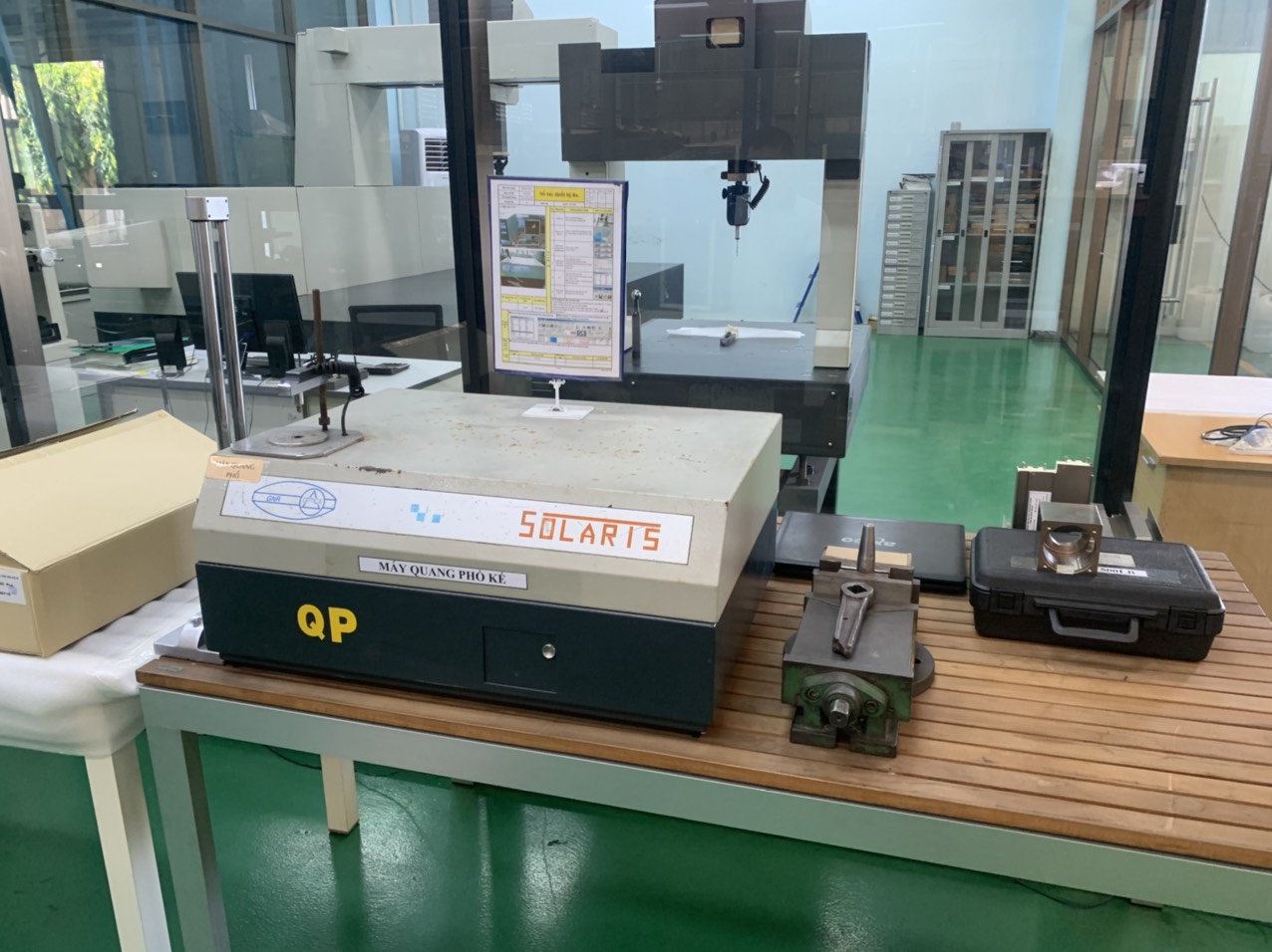
To ensure material certifications match your drawing, require mill test reports (MTRs) with each shipment, cross-check the chemical composition and mechanical properties against your specifications, and conduct incoming material inspection using portable testing equipment. Include material traceability as a contractual requirement in your purchase order.
What to Check on a Mill Test Report
A mill test report (also called a mill cert or MTR) documents the chemical and mechanical properties 2 of the specific heat of metal used. Here is what to verify:
| MTR Data Point | What to Check | Why It Matters |
|---|---|---|
| Chemical composition | Match each element to the alloy spec (e.g., ASTM, JIS) | Trace element variations affect formability and corrosion resistance |
| Tensile strength | Must fall within the specified range | Out-of-range values indicate wrong temper or grade |
| Yield strength | Must meet minimum for the application | Low yield strength means the part deforms under load |
| Elongation (%) | Must meet minimum for the forming operations | Low elongation means the material will crack during stamping |
| Heat/lot number | Must be traceable to the coil used in production | Ensures traceability if a quality issue surfaces later |
| Surface condition | Matches drawing callout (2B, 2D, BA, etc.) | Wrong finish affects plating adhesion and appearance |
Traceability and Country of Origin
Material traceability goes beyond the MTR. Some U.S. buyers face tariff implications based on the country where the metal was melted and poured. A stamping supplier in Vietnam might use imported steel from China, Korea, or Japan. Each source carries different tariff rates and compliance requirements.
We track material origin for every project. Our team maintains records from the mill certificate through receiving inspection, production, and final shipment. When a buyer needs to demonstrate compliance with ESG mandates or trade regulations, we can provide a complete paper trail.
Incoming Inspection Best Practices
Paper checks are not enough. We use portable hardness testers and XRF analyzers 3 during incoming inspection to spot-check that the physical material matches the paperwork. Chemical consistency of trace elements can vary between heats of commodity-grade metal. In high-speed automated stamping, even small variations cause erratic behavior—punches breaking, inconsistent springback compensation, and out-of-tolerance parts.
Our quality process follows a PPAP-style approach. Before mass production, we validate the first article 4 against the drawing, lock down the material source, and document everything. If the mill or heat changes, we re-validate. This discipline is what prevents non-conforming product from reaching the buyer's dock.
Which Material Compatibility Issues Should I Check Before Finalizing My Stamping Order?
A lesson our China office learned early: a buyer approved a material that stamped beautifully but could not be zinc-plated without blistering. The stamping was perfect. The plating was a disaster. Three weeks of production sat in quarantine.
Before finalizing your stamping order, verify material compatibility with all secondary operations—welding, plating, heat treating, and adhesive bonding. Also check for galvanic corrosion risk with mating parts, confirm that mill oils or surface coatings will not interfere with downstream processes, and validate that FEA simulation data matches real-world material behavior.
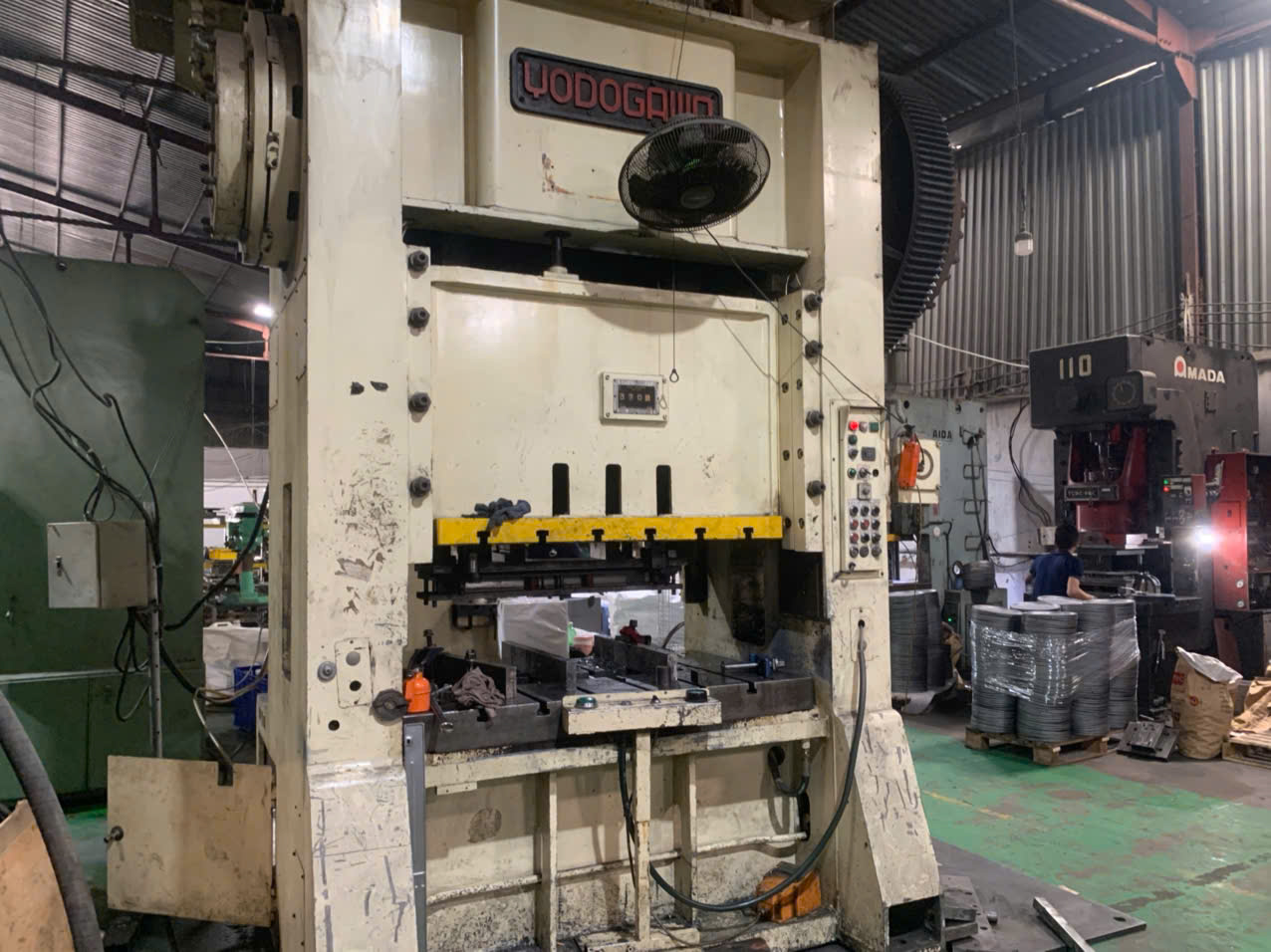
Secondary Process Compatibility
Not every material that stamps well will weld, plate, or paint well. Here are the most common compatibility issues we encounter:
Welding: Some high-strength alloys lose strength in the heat-affected zone 5 during welding. Others are prone to hot cracking. If your stamped part will be welded into an assembly, the material must be rated for the welding method (MIG, TIG, resistance) being used.
Plating and Coating: Zinc plating, tin plating, and electroless nickel 6 all have specific surface preparation requirements. Materials with certain surface hardness levels or chemical compositions may not accept coatings uniformly. The result is peeling, blistering, or uneven coverage. Mill oils left on the surface can also interfere with plating adhesion—this is why we specify cleaning requirements between stamping and plating.
Heat Treating: If a part requires post-stamping heat treatment, the material must respond predictably to the process. Certain tempers can warp or change dimensions during heat treating, creating parts that no longer fit the assembly.
Galvanic Corrosion Between Mating Materials
When a stamped bracket made of carbon steel is bolted to an aluminum housing, galvanic corrosion 7 can begin within weeks in a humid environment. The two dissimilar metals create an electrochemical cell. The more active metal (aluminum) corrodes rapidly.
Before finalizing material selection, review what the stamped part will contact in the final assembly. If dissimilar metals are involved, specify an insulating barrier, a compatible coating, or select a material that is closer on the galvanic series to its mating component. Understanding how material selection impacts durability in sheet metal fabrication can help you make more informed decisions about corrosion resistance and long-term performance.
FEA Simulation vs. Real-World Behavior
Many engineering teams rely on finite element analysis 8 to validate part designs. But FEA is only as good as the input data. If the stress-strain curves used in the simulation do not match the actual material's behavior, the model will predict one outcome while the press produces another.
We recommend that buyers request validated material data from the mill or from independent testing labs. Generic handbook values for tensile strength and elongation are a starting point, but they do not capture the specific behavior of the heat of metal you will actually use. This disconnect between digital models and production reality is a leading cause of first-article failures.
The Early Collaboration Advantage
The most effective way to avoid all of these compatibility issues is early collaboration. When our team is involved during the design phase—not after the print is released—we can flag material risks before they become expensive problems.
This Design for Manufacturability (DFM) approach works because we bring process knowledge that complements the buyer's application knowledge. The buyer knows what the part must do. We know what the material can do on a stamping press. Together, we arrive at a material choice that works in service, on the press, and in the supply chain.
Our DFM review typically covers material grade selection, bend radius validation, hole-to-bend spacing, grain direction orientation 9, springback estimation, and secondary process compatibility—all before tooling design begins. For U.S. buyers sourcing from Asia, this front-end investment in engineering collaboration is what separates a smooth launch from a months-long cycle of rework and delays.
Conclusion
Material selection pitfalls in stamping parts are preventable when you balance performance, formability, availability, and secondary process compatibility—and when you collaborate with an experienced sourcing partner early in the design phase.
Frequently Asked Questions
How Can I Avoid Choosing the Wrong Material Grade for My Stamping Parts?
A few months ago, a buyer sent us a bracket drawing specifying a high-strength stainless temper. The part geometry had tight bends and deep draws. When our engineering team ran a formability check, we knew the material would crack before the first production run finished.
What Hidden Costs Arise From Poor Material Selection in Custom Stamping Projects?
One trade-off we constantly weigh with U.S. buyers is whether a premium alloy actually adds value—or just adds cost. The answer is often surprising: the "best" material on paper can be the most expensive mistake in production.
How Do I Ensure My Supplier's Material Certifications Match My Drawing Requirements?
During a recent supplier audit at a stamping factory in Vietnam, we discovered that the material test report on file did not match the alloy grade called out on the buyer's drawing. The supplier had substituted a similar—but not identical—grade without notifying anyone. This is more common than most buyers realize.
Footnotes
1. Defines yield strength as a critical mechanical property for determining material performance under stress. ↩︎
2. Provides an overview of mill test reports and their role in verifying material specifications. ↩︎
3. Authoritative Wikipedia page explaining X-ray fluorescence technology. ↩︎
4. Authoritative Wikipedia definition of the production validation process. ↩︎
5. Defines the heat-affected zone and its impact on the mechanical properties of welded components. ↩︎
6. Comprehensive Wikipedia overview of the electroless nickel plating process. ↩︎
7. Describes the electrochemical process of galvanic corrosion when dissimilar metals are in contact. ↩︎
8. Authoritative Wikipedia entry explaining the simulation method. ↩︎
9. Explains how grain orientation affects the formability and structural integrity of sheet metal during stamping. ↩︎