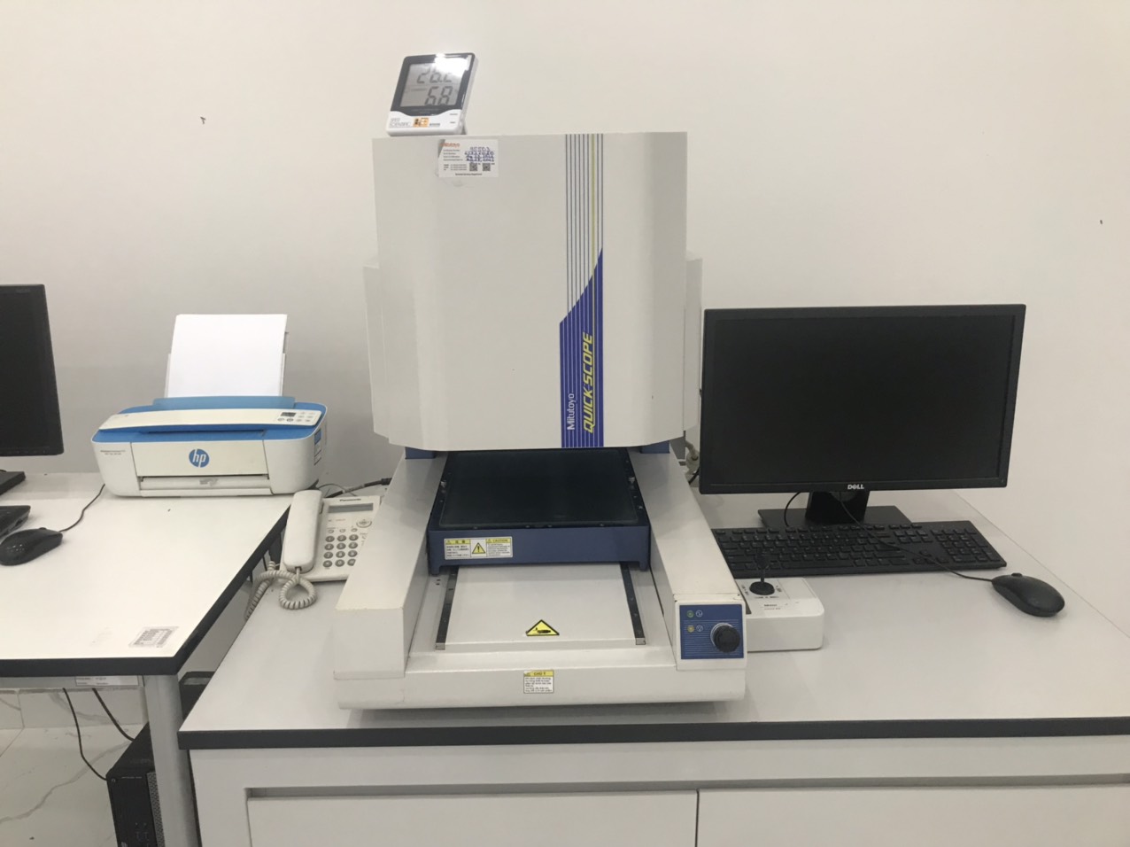
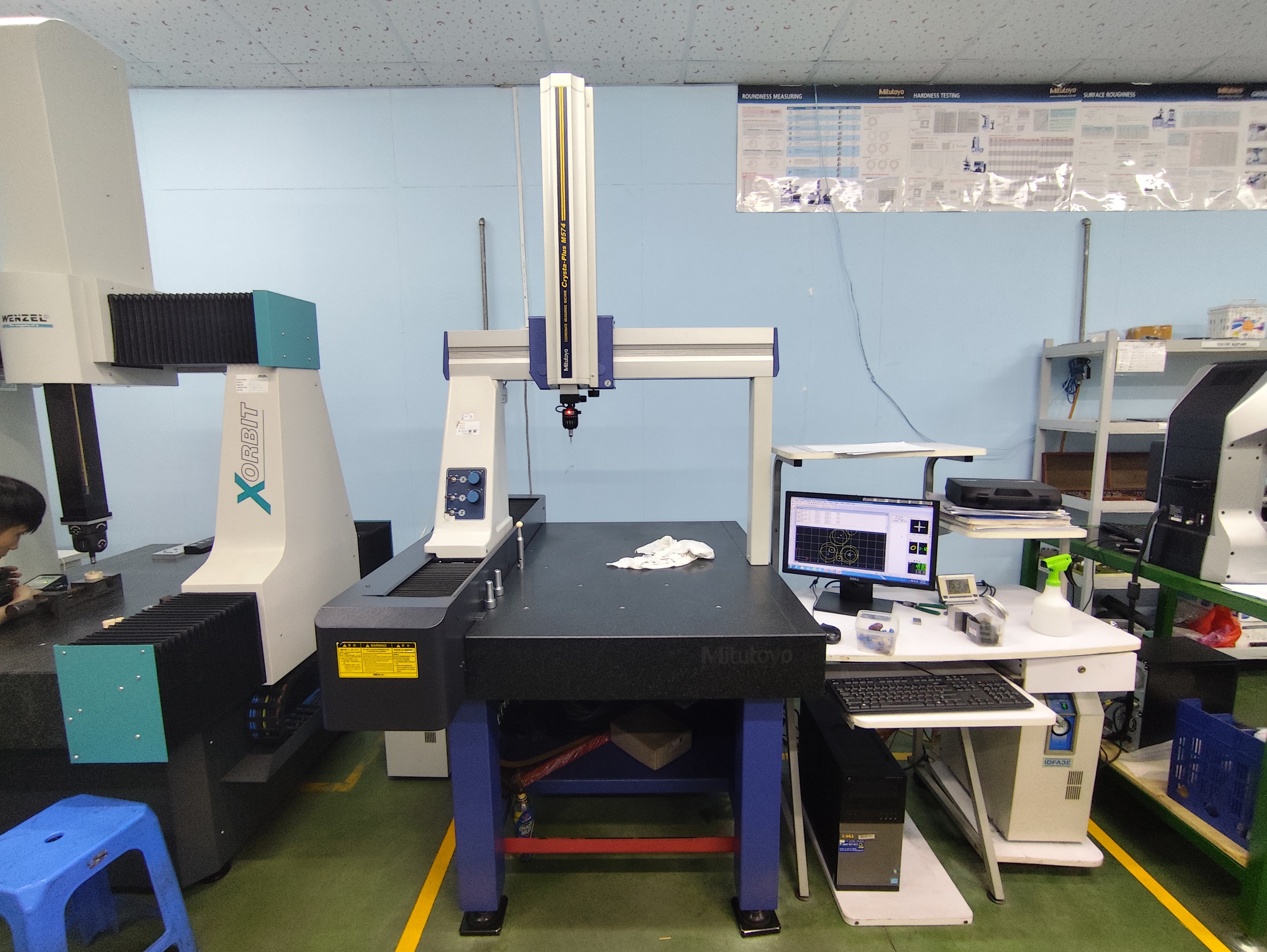
Every rejected sheet metal part we trace back to our suppliers starts with the same root cause — someone measured it wrong, or didn’t measure it at all.
Sheet metal dimensional inspection uses a hierarchy of measuring tools — from calipers, micrometers, and sheet metal gauges for basic checks, to Coordinate Measuring Machines (CMM) and laser scanning systems for high-precision validation, plus specialized protractors and fixtures for bend angle verification on complex custom parts.
Getting the right answer from the right tool matters more than most buyers realize. Below, we break down exactly which tools your supplier should use, when each one applies, and how to tell if your sourcing partner’s metrology equipment 1 is up to the job.
Which essential hand tools should my supplier use to verify my sheet metal dimensions?
A client once sent us a drawing calling out ±0.05 mm on a bracket flange — and the supplier had nothing on the shop floor but a steel tape measure and a scratched-up ruler.
Your supplier should use digital calipers for internal and external dimensions, micrometers for precise thickness readings, a sheet metal gauge for material verification, bevel protractors for angle checks, and height gauges for step and depth features — at minimum.

Hand tools are the first line of defense in any quality control program 2. They are fast, portable, and cheap. But they only work if the right tool is matched to the right feature. Let me walk you through the essentials we expect on every supplier's shop floor.
Digital Calipers
Digital calipers 3 are the workhorse of sheet metal inspection. They handle outside dimensions, inside dimensions, and depth measurements. A good pair reads to 0.01 mm. We require our suppliers to use name-brand calipers — Mitutoyo, Starrett, or equivalent — because cheap calipers drift quickly. One critical limitation: on very thin sheet metal, the jaw profile can sit on the edge burr instead of the true surface, which introduces error.
Micrometers and Thickness Gauges
Micrometers give you the most reliable thickness reading on sheet metal. A standard outside micrometer 4 with flat anvils clamps the material and reads to 0.001 mm. For quick go/no-go thickness checks, a simple sheet metal gauge 5 — the slotted tool where you slide the sheet into graduated slots — confirms material grade fast. Our Vietnam team uses both during incoming material inspection before any fabrication begins.
Angle and Flatness Tools
Bevel protractors 6 measure angles that calipers cannot. A speed square is handy for verifying 90° bends on the spot. For flatness inspection, a precision straight edge paired with feeler gauges gives a quick read on warpage. A spirit level works for large panels but lacks the resolution needed for tight dimensional tolerances.
| Hand Tool | Best Use | Typical Resolution | Limitation |
|---|---|---|---|
| Digital Calipers | Length, width, hole diameter | 0.01 mm | Edge burr can cause false readings on thin stock |
| Outside Micrometer | Material thickness | 0.001 mm | Measures only one point at a time |
| Sheet Metal Gauge | Quick thickness verification | Per gauge number | No decimal precision; go/no-go only |
| Bevel Protractor | Angle measurement | 0.08° (5 arc-min) | Operator-dependent alignment |
| Height Gauge | Step height, depth features | 0.01 mm | Requires a flat reference surface |
| Feeler Gauge + Straight Edge | Flatness inspection | 0.02 mm | Manual, slow for large parts |
When Hand Tools Are Not Enough
Hand tools suffer from two fundamental problems: speed and operator error. When a supplier checks 50 dimensions on a bracket using calipers alone, it takes time. And each reading depends on the operator's technique — how they hold the caliper, how they position the jaws, whether they zero the tool before each measurement. In our experience managing suppliers across Vietnam and other Asian countries, we often find that two different operators measuring the same feature get different numbers. That is why hand tools are necessary but not sufficient. They handle first-article spot checks and in-process monitoring, but they cannot replace the repeatability of a machine-driven system for final inspection.
How can I ensure high-precision accuracy for my parts using CMM or laser scanning?
Last quarter, we audited a supplier who claimed "full CMM capability" — but their machine sat in an un-air-conditioned corner of the factory, and the last calibration certificate 7 was two years old.
To ensure high-precision accuracy, require your supplier to use a calibrated Coordinate Measuring Machine (CMM) in a temperature-controlled environment for critical dimensions, and supplement it with laser scanning or portable measuring arm systems for full-surface deviation analysis against your CAD model.
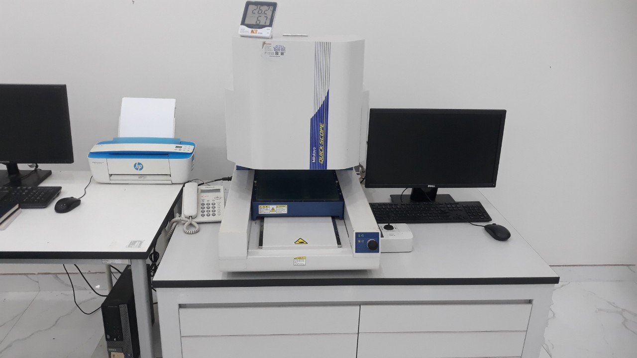
CMM inspection 8 is the gold standard in aerospace and automotive sheet metal validation. But "having a CMM" and "using it properly" are very different things. Here is what actually matters.
Traditional Stationary CMMs
A traditional CMM uses a precision stylus — a ruby-tipped probe — to touch discrete points on the part surface. The machine records each point in 3D coordinates and compares them to the nominal CAD geometry. The result is a dimensional report showing actual values, nominal values, and deviations. These machines sit on vibration-isolated granite tables in climate-controlled metrology labs. Temperature matters because metal expands. A 1°C shift can move readings on a 500 mm part by several microns.
However, there is a key limitation many buyers overlook. CMMs measure points, not surfaces. The stylus touches one spot at a time. If the part has a subtle warp between probe points, the CMM misses it. And on thin sheet metal, the probe contact force can actually deflect the part, producing a false reading. We always ask our suppliers what probe force they use and whether they fixture the part properly to avoid this.
Portable CMM Arms
Portable measuring arm systems 9 bring CMM-level inspection to the shop floor. They achieve accuracies around 30 μm (0.03 mm), which is sufficient for most commercial sheet metal work. The operator guides the arm by hand, touching features or sweeping a laser scanner head across the surface. The big advantage: the part stays where it is. No transport to a lab, no risk of deformation during handling. We have seen large enclosure panels that measured in-spec on the production floor but failed in a distant lab — because the part flexed during shipping.
3D Laser Scanning and Vision Systems
Laser scanning 10 generates dense point clouds — millions of data points across the entire surface. This reveals deformations, warpage, and surface deviations that probing alone cannot catch. Modern systems compare the scan directly to the CAD model and produce color-mapped deviation reports. These reports are incredibly useful for our U.S. clients because they show at a glance where the part is in tolerance and where it drifts.
Specialized scanners like the Zeiss ATOS Q address a persistent challenge: measuring thin sheet metal edges. Traditional scanners struggle with edge location because the laser reflects unpredictably off sharp edges. The ATOS Q uses gray value features — essentially reading 2D photographs to locate holes and edges by color contrast — rather than relying on edge scanning alone. It also includes a touch probe accessory for simple geometric features.
| Inspection Method | Accuracy | Best For | Key Limitation |
|---|---|---|---|
| Stationary CMM | 1–5 μm | Critical tolerances, GD&T validation | Requires controlled lab; misses surface deformations between probe points |
| Portable CMM Arm | ~30 μm | On-floor inspection, large parts | Sensitive to bumps; calibration can drift if mishandled |
| 3D Laser Scanner | 10–50 μm depending on system | Full-surface deviation maps, complex geometry | Struggles with shiny or reflective surfaces and deep cavities |
| Optical Comparator | 5–10 μm on projected profile | 2D profile checks, hole patterns | Limited to flat or near-flat features |
The Hybrid Approach We Recommend
The industry trend — and what we push our supplier partners toward — is a hybrid method. Use tactile probing for critical dimensions: hole positions, slot widths, mounting surfaces with tight dimensional tolerances. Then use laser scanning for the surrounding geometry: overall shape, flatness, warp. This combination optimizes both accuracy and speed. The probe gives you hard numbers on critical features. The scan gives you a visual map of everything else. When we manage PPAP documentation for our clients, this hybrid data set provides the most complete evidence of conformance.
What specific tools are needed to measure the complex angles and bends in my custom design?
One of the trickiest inspection tasks we handle involves brackets with multiple bends at compound angles — the kind where a one-degree error on the first bend cascades into a three-millimeter gap at the final mating surface.
For complex angles and bends, your supplier needs digital bevel protractors for individual bend angle verification, radius gauges for inside bend radii, CMM or 3D scanning for compound angle validation, and checking fixtures for high-volume go/no-go confirmation of the finished form.
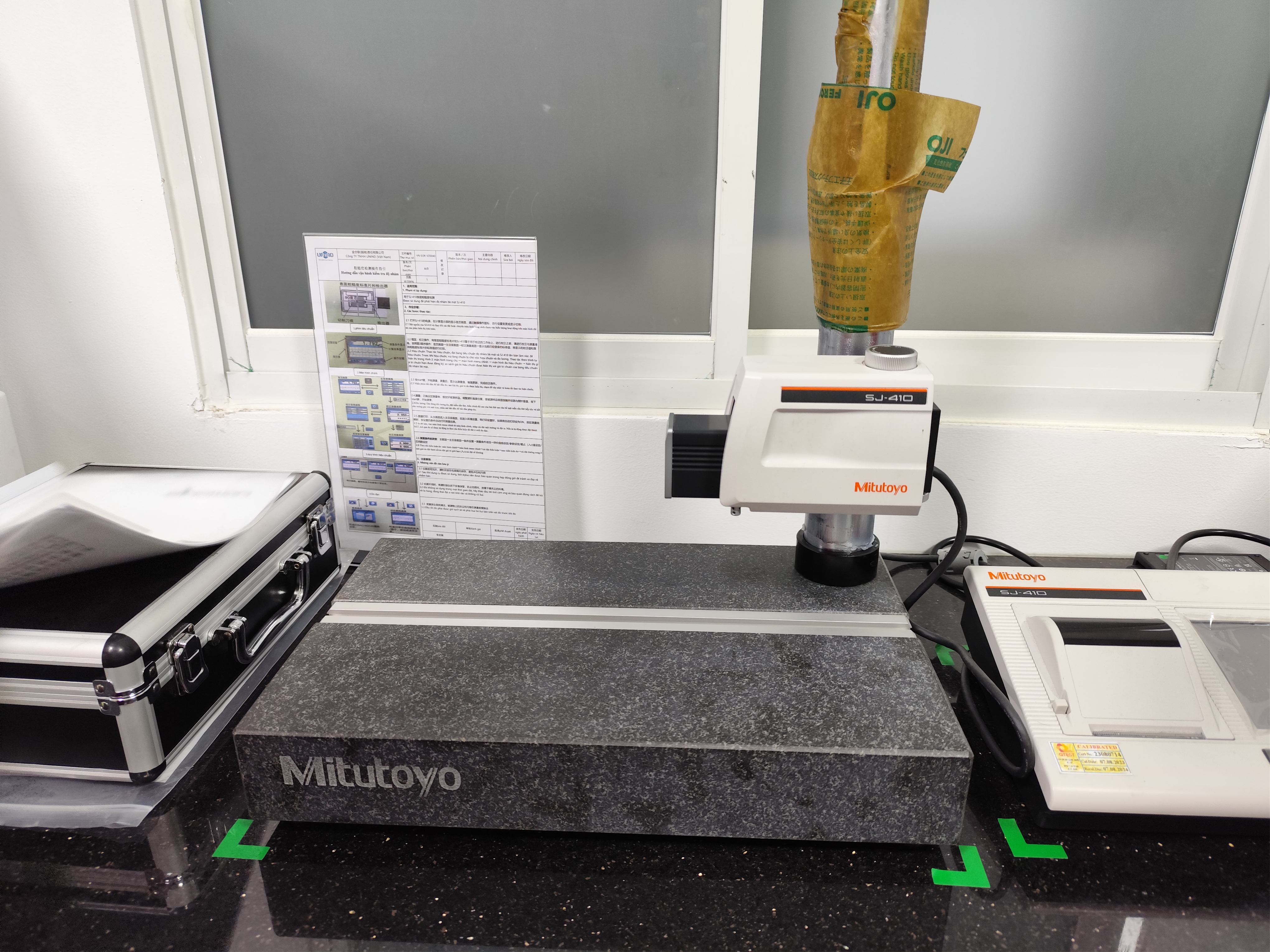
Sheet metal bending introduces variables that flat-part inspection tools simply cannot address. Springback, overbend compensation, and material grain direction all affect the final angle. Here is how to measure what matters.
Bend Angle Verification
A digital bevel protractor is the simplest tool for checking a single bend angle. The operator places it against both flanges and reads the angle directly. Resolution is typically 0.1° or better. For production environments, backlit digital models make reading faster and reduce errors.
But single-point angle measurement has a catch. Sheet metal flanges are not always perfectly flat after bending. If one flange has a slight bow, the protractor reading changes depending on where you place it. That is why we insist suppliers check angles at multiple points along the bend line — near both ends and at the center.
Radius Gauges
The inside bend radius affects both the angle and the strength of the part. A set of radius gauges — thin metal templates with known radii — lets the operator check the bend radius by holding the gauge against the inside of the bend and looking for a light gap. No light gap means good fit. This is a low-tech method, but it works.
Checking Fixtures for Complex Forms
For high-volume production of parts with multiple bends, checking fixtures are the most efficient solution. A fixture is a custom-machined tool shaped to match the final part geometry. The operator drops the part into the fixture. If it sits flush, it passes. If it rocks or gaps appear, it fails. This go/no-go method requires virtually no training and takes seconds per part.
We have helped U.S. clients develop checking fixtures for brackets that have four or five bends. The fixture checks every bend simultaneously — angle, position, and orientation — in one physical action. The tradeoff is cost: a good fixture can run several thousand dollars, so it only makes economic sense above certain production volumes.
3D Methods for Compound Angles
When a part has bends in multiple planes — like a Z-bracket or a twisted mounting arm — no single protractor reading captures the full picture. Here, a portable measuring arm or 3D scanner is essential. The system captures the entire 3D shape and compares it to the CAD model. Deviation maps show exactly where each bend drifts from nominal. This is the approach we use during first-article inspection for complex custom parts before approving full production.
| Bend Measurement Need | Recommended Tool | Speed | Cost |
|---|---|---|---|
| Single bend angle | Digital bevel protractor | Fast (seconds) | Low (~$50–$200) |
| Inside bend radius | Radius gauge set | Fast (seconds) | Low (~$30–$100) |
| Multiple bends, high volume | Checking fixture (go/no-go) | Very fast (seconds) | High (custom tooling) |
| Compound angles, complex 3D form | Portable CMM arm or 3D scanner | Moderate (minutes) | High (equipment investment) |
| Flatness of flanges after bending | Straight edge + feeler gauge | Moderate | Low |
The Real-World Challenge: Springback
Every sheet metal bend springs back slightly after the press brake releases. The amount of springback depends on the material type, thickness, bend radius, and grain direction. A supplier who does not account for springback will consistently produce parts that are a degree or two off nominal. During our supplier audits, we check whether the press brake operator uses springback compensation tables or empirical test bends. The measurement tool catches the error — but the process control prevents it.
How do I evaluate if my sourcing partner's inspection equipment meets my strict quality standards?
During a recent supplier qualification visit in Vietnam, we walked through a machine shop that had invested in a brand-new portable measuring arm — still in its shipping case, unopened, three months after delivery.
Evaluate your sourcing partner's inspection capability by verifying current calibration certificates for all metrology equipment, confirming trained operators with documented procedures, checking that measurement capability matches your tightest dimensional tolerances, and reviewing actual inspection reports from recent production runs.

Owning metrology equipment is not the same as using it effectively. Here is a structured approach we use when auditing suppliers on behalf of our U.S. and European clients.
Step 1: Check the Equipment List Against Your Part Requirements
Start with your drawing. Identify the tightest tolerance, the most complex feature, and the critical-to-function dimensions. Then ask: does the supplier have the right tool for each one? If your part has a ±0.05 mm position tolerance on a hole pattern, calipers will not cut it. You need a CMM or at least an optical comparator. If your part has multiple bends in three planes, a bevel protractor alone is insufficient — you need 3D measurement capability.
Step 2: Verify Calibration Status
Every measuring instrument drifts over time. Calibration ensures the tool reads true. We check for:
- A current calibration certificate from an accredited lab (ISO/IEC 17025).
- Calibration intervals appropriate to the tool type (typically annual for calipers, semi-annual for CMMs).
- Calibration stickers on the equipment matching the certificate dates.
If a supplier cannot produce calibration records on request, that is an immediate red flag. In our experience, this is one of the most common gaps we find during audits.
Step 3: Assess Operator Competence
A CMM is only as good as its operator and program. We look for documented training records. We ask the operator to demonstrate a measurement on a sample part. We watch their technique with calipers — do they zero the tool? Do they take multiple readings? Do they record results in a structured format?
Step 4: Review Actual Inspection Reports
Ask for inspection reports from the last three production runs. A good report includes:
- Part number and revision
- Feature ID mapped to the drawing
- Nominal value, measured value, tolerance, and pass/fail status
- Operator name and date
- Equipment used (with serial number)
If the supplier only provides a generic "QC Passed" stamp with no data, you have no evidence of actual dimensional verification. We generate full PPAP-level inspection documentation for our clients, including balloon drawings, dimensional reports, and capability studies when required.
Step 5: Match Measurement Capability to Tolerance
A useful rule: your measurement tool's resolution should be at least 10 times finer than the tolerance it is checking. This is sometimes called the 10:1 rule of metrology. For a ±0.1 mm tolerance, you need a tool that reads to 0.01 mm or better. For ±0.01 mm, you need equipment resolving to 0.001 mm. Understanding how to communicate OEM tolerance requirements to sheet metal fabrication suppliers is essential to ensuring the right measurement capability is in place.
| Your Tolerance | Minimum Tool Resolution | Recommended Equipment |
|---|---|---|
| ±1.0 mm | 0.1 mm | Steel rule, tape measure |
| ±0.25 mm | 0.025 mm | Digital calipers |
| ±0.1 mm | 0.01 mm | Digital calipers, height gauge |
| ±0.05 mm | 0.005 mm | Micrometer, CMM |
| ±0.01 mm | 0.001 mm | CMM, optical comparator |
Integration with CAD and Digital Reporting
Modern quality control increasingly requires digital traceability. We look for suppliers who can export CMM or scan data in formats compatible with CAD systems — IGES, STEP, or native scanner formats. Color-mapped deviation reports overlaid on the CAD model are particularly valuable. They let your engineering team see exactly where the part conforms and where it drifts, without interpreting rows of numbers. Some of our clients use this data to feed digital twin models for predictive quality control and design optimization on future revisions.
In-Line vs. Lab-Based Inspection
There is a growing shift toward in-line and near-line inspection — placing measurement equipment on or near the production floor rather than in a separate lab. This reduces handling, eliminates deformation risk during transport, and provides real-time feedback to the operator. When we evaluate a supplier, we consider whether their inspection flow matches their production flow. A supplier running 10,000 brackets per month should not be carrying every part to a distant lab. They need floor-level tools — checking fixtures, portable arms, or automated 2D planar inspection systems — that keep pace with production. For a broader look at what to assess, see our guide on key quality inspection steps for finished sheet metal products.
Conclusion
Choosing the right measuring tools for sheet metal dimensional inspection comes down to matching your part's tolerances, geometry, and production volume to the correct equipment — and then verifying your supplier actually uses it properly, with calibration, training, and documented results.
Frequently Asked Questions
Which essential hand tools should my supplier use to verify my sheet metal dimensions?
A client once sent us a drawing calling out ±0.05 mm on a bracket flange — and the supplier had nothing on the shop floor but a steel tape measure and a scratched-up ruler.
How can I ensure high-precision accuracy for my parts using CMM or laser scanning?
Last quarter, we audited a supplier who claimed "full CMM capability" — but their machine sat in an un-air-conditioned corner of the factory, and the last calibration certificate 7 was two years old.
What specific tools are needed to measure the complex angles and bends in my custom design?
One of the trickiest inspection tasks we handle involves brackets with multiple bends at compound angles — the kind where a one-degree error on the first bend cascades into a three-millimeter gap at the final mating surface.
Footnotes
1. Defines metrology equipment and its importance in ensuring product quality and safety. ↩︎
2. Explains what a quality control program is and its role in meeting product standards. ↩︎
3. Authoritative (Wikipedia) source providing a comprehensive overview of calipers, including digital calipers, their resolution, and accuracy. ↩︎
4. Authoritative (Wikipedia) source defining micrometers, detailing outside micrometers, their use, and components. ↩︎
5. Explains what sheet metal gauge is and its importance for determining material thickness in fabrication. ↩︎
6. Provides information on the uses, functions, and applications of bevel protractors for angle measurement. ↩︎
7. Explains what a calibration certificate is and its importance for verifying instrument accuracy and compliance. ↩︎
8. Provides a comprehensive overview of CMM inspection, its process, and applications in manufacturing. ↩︎
9. Describes portable CMM arms as flexible tools for on-site inspection and measurement. ↩︎
10. Explains 3D laser scanning technology, how it works, and its applications in capturing precise object data. ↩︎