

A single rejected stamping part once cost one of our U.S. clients a full week of assembly downtime — and that experience taught our team at DEWIN that quality requirements for automotive stamping parts are not just paperwork.
Quality requirements for automotive stamping parts include IATF 16949 certification, dimensional tolerances often as tight as ±0.05 mm, flawless surface finishes, full material traceability, and mandatory use of the five Automotive Quality Core Tools — APQP, PPAP, FMEA, MSA, and SPC — to enforce a zero-defect mentality across every production run.
Below, I break down the specific standards, tolerances, inspection methods, and approval processes you need to specify — and verify — before signing off on any supplier. Each section reflects lessons we have learned managing stamping projects across Asia for American buyers.
How can I ensure my automotive stamping supplier meets IATF 16949 requirements?
One trade-off we constantly weigh during supplier audits in Vietnam and China is whether a factory's ISO 9001 1 certificate alone is enough — and for automotive work, the answer is always no.
To ensure your stamping supplier meets IATF 16949 requirements, verify third-party certification from an IATF-recognized body, confirm implementation of the five Automotive Quality Core Tools (APQP, PPAP, FMEA, MSA, SPC), and conduct regular on-site audits focused on defect prevention rather than detection alone.

Why IATF 16949 Is Not Just an Upgraded ISO 9001
Many purchasing managers assume that if a supplier holds ISO 9001, the jump to IATF 16949 is small. It is not. ISO 9001 is a universal quality management system. It asks: "Do you have a process?" IATF 16949 asks: "Does your process actively prevent defects?" The standard demands Statistical Process Control on critical dimensions, Measurement System Analysis for every gauge, and a full Failure Mode and Effects Analysis before a single production die is cut.
When our team audits a stamping factory, we check five layers. First, we confirm the IATF 16949 certification 2 is current and issued by a recognized body — self-certification is not accepted anywhere in the automotive supply chain. Second, we review the factory's Advanced Product Quality Planning 3 documentation to see how they translate a customer drawing into a process flow. Third, we examine their SPC charts for at least three months of historical data on critical-to-quality dimensions. Fourth, we ask to see their MSA studies, specifically Gage R&R results that prove the measurement system can actually resolve the tolerances on the print. Fifth, we walk the production floor to verify that operators follow the control plan in real time.
ISO 9001 vs. IATF 16949: A Quick Comparison
| Criterion | ISO 9001 | IATF 16949 |
|---|---|---|
| Scope | General manufacturing | Automotive production and service parts |
| Defect approach | Detection and correction | Prevention before occurrence |
| Core tools required | None mandated | APQP, PPAP, FMEA, MSA, SPC |
| Certification body | Any accredited registrar | Must be IATF-recognized |
| Process capability | Not specified | Cpk ≥ 1.67 for critical characteristics |
| Supplier audit depth | Periodic review | Risk-based layered audits |
What Happens When Certification Is Missing
I have seen U.S. buyers accept a supplier's claim of "working toward IATF" only to discover, after tooling investment, that the factory lacks basic die maintenance protocols and cannot hold a Cpk above 1.0. At that point, correcting the problem costs more than starting over. Our recommendation is simple: verify before you invest.
What tolerances should I specify to avoid dimensional defects in stamped parts?
A buyer we work with in the Midwest recently sent us drawings for a structural mounting bracket with only default ISO 2768 medium tolerances noted — and then wondered why the first samples did not fit the robotic welding cell.
For safety-critical automotive stamping parts, specify explicit tolerances — often ±0.05 mm on critical features — using Geometric Dimensioning and Tolerancing (GD&T) symbols on every drawing, and require your supplier to demonstrate process capability with a Cpk of at least 1.67 before mass production begins.
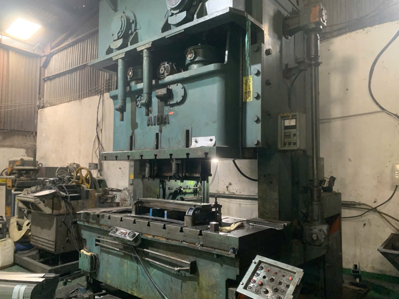
Why Default Tolerances Fail in Automotive
Default tolerance tables like ISO 2768 were designed for general mechanical parts. They assume that a ±0.3 mm window on a 50 mm feature is acceptable. In automotive assembly — especially when parts feed into robotic weld fixtures or automated fastening stations — that window is far too wide. A 0.2 mm shift on a hole position can mean a bolt misses its weld nut, and the entire body-in-white station stops.
Our engineering team always reviews incoming drawings and flags features where the tolerance must be tightened beyond the default. We then confirm with the client which dimensions are critical-to-quality (CTQ) and which can remain at standard levels. This saves cost on inspection while protecting fit and function.
Key Dimensional Accuracy Standards for Stamped Parts
| Feature Type | Typical Automotive Tolerance | Measurement Method |
|---|---|---|
| Hole position | ±0.05 mm – ±0.10 mm | CMM or optical comparator |
| Profile of surface | ±0.10 mm | 3D scanning |
| Flatness (EV battery plates) | < 0.1 mm over full surface | CMM with surface map |
| Hole diameter | ±0.02 mm – ±0.05 mm | Pin gauge or CMM |
| Bend angle | ±0.5° | Protractor gauge or CMM |
| Edge burr height | ≤ 0.1 mm | Burr height gauge |
Dealing with Springback in Advanced High-Strength Steels
Springback is a persistent challenge. When a stamping die forms a part from Advanced High-Strength Steel 4 exceeding 980 MPa tensile strength, the material wants to "spring" back toward its original shape after the press opens. The result is a part that looks correct in the die but measures out of tolerance on the CMM.
Our approach during die tryout is to work with the toolmaker on springback compensation. The die geometry is intentionally over-bent so the part relaxes into the correct angle. This requires iterative simulation and physical verification, and it is one reason we insist on a thorough die-tryout phase before any Production Part Approval Process submission. Tensile strength testing of every incoming coil also helps us predict springback behavior lot by lot.
Burr height specifications are another detail that many buyers overlook. A burr taller than 0.1 mm can cut an operator's hand during assembly, damage mating surfaces, or interfere with sealing gaskets. We specify burr limits on every blanking and piercing operation and verify them with dedicated gauges.
Sheet Metal Forming Limits and Their Role
Understanding sheet metal forming limits is essential for setting realistic tolerances. Every material has a forming limit diagram (FLD) that shows how far it can stretch before it cracks. If a part geometry pushes the material beyond its FLD, no amount of tolerance specification will save it — the part will split. During our APQP phase, we review the part geometry against the material's FLD and flag any risk areas before tooling begins.
Which inspection methods help me verify weld and surface quality on stamped components?
During a recent final inspection at a factory in southern China, our QC engineer caught a hairline scratch on a powder-coated bracket that the factory's own inspectors had passed — a reminder that surface defect inspection requires both the right tools and the right eyes.
To verify weld and surface quality on stamped components, use a combination of visual inspection under controlled lighting, 3D scanning for profile deviations, Coordinate Measuring Machines for dimensional checks, destructive weld testing for joint strength, and real-time in-die sensing for high-volume production monitoring.
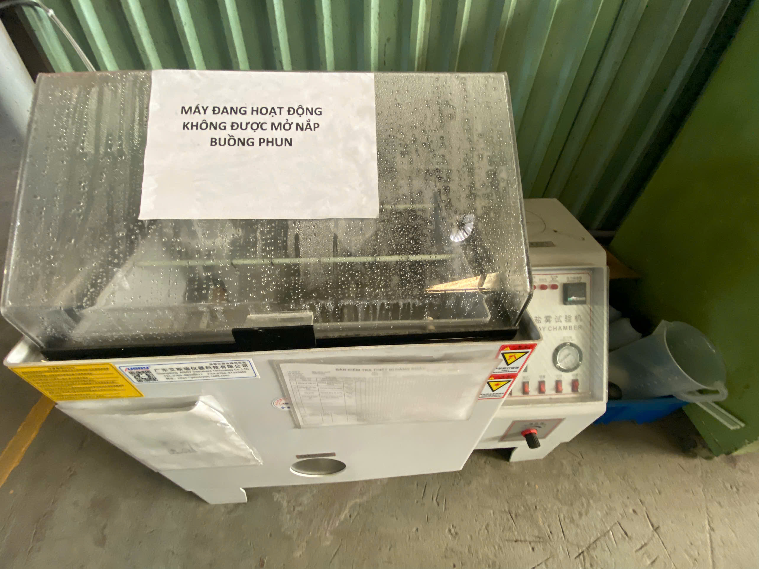
Visual and Surface Inspection
Surface quality for automotive stampings is categorized by visibility. Class A surfaces — exterior body panels — demand zero-defect finishes. No orange peel, no scratches, no microscopic pimples. Interior structural brackets like the ones we commonly manage still require smooth surfaces free of wrinkles, dents, and deep tool marks. Even a minor surface imperfection on a structural part can become a stress concentrator under fatigue loading.
Our inspectors use controlled directional lighting (highlight inspection) to reveal surface defects 5 that are invisible under diffuse shop lighting. For coated parts, we also check coating adhesion with cross-hatch tape tests and measure film thickness with a digital gauge.
Weld Quality Verification
Many automotive stamping assemblies include secondary welding — MIG, TIG, or resistance spot welds that join stamped components into sub-assemblies. Verifying weld quality is just as important as verifying the stampings themselves.
| Inspection Method | What It Checks | When to Use |
|---|---|---|
| Visual weld inspection | Surface porosity, undercut, spatter | Every part, 100% |
| Destructive peel/chisel test | Weld nugget size and penetration | First article and periodic batch |
| Cross-section macro test | Fusion zone and heat-affected zone | PPAP and periodic audit |
| Ultrasonic testing | Internal voids in welds | Safety-critical joints |
| Pull/shear test | Joint strength (kN) | First article and SPC tracking |
Advanced Metrology: CMM and 3D Scanning
For dimensional verification, our teams use portable CMM arms 6 and structured-light 3D scanners. The CMM gives us point-by-point data on specific GD&T features. The 3D scanner gives us a full color-map deviation report that shows, at a glance, where the part deviates from the CAD model. For more detail on how these tools fit into a procurement workflow, see our guide on dimensional measurement and CMM inspection standards for stamping parts.
3D scanning is especially useful during die tryout. We can overlay the scan data on the nominal model and identify areas where the die needs adjustment — often before we even run a full measurement report. This accelerates the approval cycle and reduces the number of tryout loops.
Emerging Inspection Technologies
Real-time acoustic emission monitoring is an emerging technology that can detect micro-fractures and tool-wear signatures invisible to traditional vision systems. In-die sensing monitors slug detection, part ejection, and material feed accuracy during each press stroke. These technologies are becoming requirements for high-volume runs because they prevent catastrophic tool damage and scrap accumulation.
Product Carbon Footprint Considerations
Increasingly, quality requirements extend beyond the physical part. Several of our European-bound projects now require Product Carbon Footprint 7 data, documenting the energy intensity and recycled content of each stamping. This trend is moving into the U.S. market as well, and forward-thinking purchasing managers are starting to include PCF clauses in their supplier agreements.
How do I confirm my supplier follows PPAP and first article inspection before mass production?
A lesson we learned early in our supply-chain management work: a supplier who skips the Production Part Approval Process almost always delivers problems at scale.
Confirm PPAP compliance by requiring your supplier to submit all 18 PPAP elements — including dimensional results, material certifications, process capability studies, MSA reports, and a signed Part Submission Warrant — and verify first article inspection data against your drawing before authorizing mass production release.

What PPAP Actually Includes
PPAP is not a single document. It is a package of 18 elements that together prove the supplier can consistently produce parts that meet your specification. Many buyers request only a "Level 3" submission, which includes the Part Submission Warrant, dimensional results, material test reports, and appearance approval. But even at Level 3, the supplier must have completed all 18 elements internally.
Here is a practical overview of the key PPAP elements relevant to stamped parts:
The 18 PPAP Elements: Stamping Focus
| Element | What It Covers | Stamping Relevance |
|---|---|---|
| 1. Design records | Customer drawing and specs | Confirm latest revision |
| 2. Engineering change documents | Any deviations or changes | Track revision history |
| 3. Customer engineering approval | If required | For design-responsible suppliers |
| 4. Design FMEA | Potential design failure modes | If supplier owns design |
| 5. Process flow diagram | Step-by-step process | Blanking → forming → trimming → welding |
| 6. Process FMEA | Potential process failure modes | Die wear, material feed errors, springback |
| 7. Control plan | What, how, and how often to check | CTQ features, SPC frequency |
| 8. MSA studies | Gage R&R for all measurement systems | CMM, pin gauges, height gauges |
| 9. Dimensional results | Full layout of all features | CMM or 3D scan report |
| 10. Material test results | Chemical and mechanical properties | Tensile strength, hardness, composition |
| 11. Initial process studies | Cpk and Ppk calculations | Must meet Cpk ≥ 1.67 for critical dims |
| 12. Qualified lab documentation | Lab accreditation | ISO 17025 preferred |
| 13. Appearance Approval Report | Visual standards sign-off | Surface finish, coating quality |
| 14. Sample parts | Physical samples | Typically 5 pieces from production run |
| 15. Master sample | Retained reference part | Stored for life of part |
| 16. Checking aids | Fixtures, go/no-go gauges | Custom check fixtures for complex forms |
| 17. Customer-specific requirements | OEM-unique clauses | Varies by end customer |
| 18. Part Submission Warrant (PSW) | Formal sign-off document | Signed by supplier quality manager |
First Article Inspection in Practice
First article inspection (FAI) is the detailed measurement of the first production parts off the actual production tooling, using the actual production process. It is not a prototype check. It is not a measurement from a different machine. The entire point is to confirm that this die, on this press, with this material, produces parts within specification.
Our standard practice is to witness the first article run at the supplier's facility. We bring our own portable CMM arm and run an independent measurement alongside the supplier's data. If the numbers match and all dimensions fall within tolerance, we sign off. If they do not, we work with the supplier to identify root causes — often related to die adjustment, material lot variation 8, or press parameter settings — before any mass production begins. To learn how to build a robust framework for evaluating parts at receiving, see our article on how to establish effective incoming inspection standards for stamping parts.
Material Traceability Through PPAP
Material traceability is a non-negotiable element. Every stamped part must trace back to the original steel or aluminum coil, including the heat number 9, chemical composition, and mechanical property test results. We verify that the supplier's material certificates match the actual coil used during the PPAP run. This prevents a common problem: suppliers qualifying PPAP with premium material and then switching to a cheaper grade during mass production. Understanding how to specify quality standards and acceptance terms for sourcing stamping parts upfront is the best way to guard against this risk.
Conclusion
Quality requirements for automotive stamping parts span certifications, tolerances, inspections, and formal approval processes — and every layer matters. If you need a partner who manages these details across Asian supply chains, reach out to our team at DEWIN.
Frequently Asked Questions
How can I ensure my automotive stamping supplier meets IATF 16949 requirements?
One trade-off we constantly weigh during supplier audits in Vietnam and China is whether a factory's ISO 9001 1 certificate alone is enough — and for automotive work, the answer is always no.
What tolerances should I specify to avoid dimensional defects in stamped parts?
A buyer we work with in the Midwest recently sent us drawings for a structural mounting bracket with only default ISO 2768 medium tolerances noted — and then wondered why the first samples did not fit the robotic welding cell.
Which inspection methods help me verify weld and surface quality on stamped components?
During a recent final inspection at a factory in southern China, our QC engineer caught a hairline scratch on a powder-coated bracket that the factory's own inspectors had passed — a reminder that surface defect inspection requires both the right tools and the right eyes.
Footnotes
1. The ISO official site defines the core requirements for quality management systems globally. ↩︎
2. The official IATF site provides the definitive standard for automotive quality management systems. ↩︎
3. Wikipedia details the APQP framework used in the automotive industry for product development. ↩︎
4. WorldAutoSteel defines Advanced High-Strength Steel grades used in modern automotive stamping. ↩︎
5. The Department of Energy discusses advanced surface inspection systems for manufacturing quality control. ↩︎
6. Wikipedia provides a technical overview of Coordinate Measuring Machines used for precision dimensional inspection. ↩︎
7. The ISO 14067 standard specifies requirements for quantifying the carbon footprint of products. ↩︎
8. NIST provides standards for material measurement and variation analysis in industrial manufacturing. ↩︎
9. Wikipedia explains the heat number system used for material traceability in steel production. ↩︎