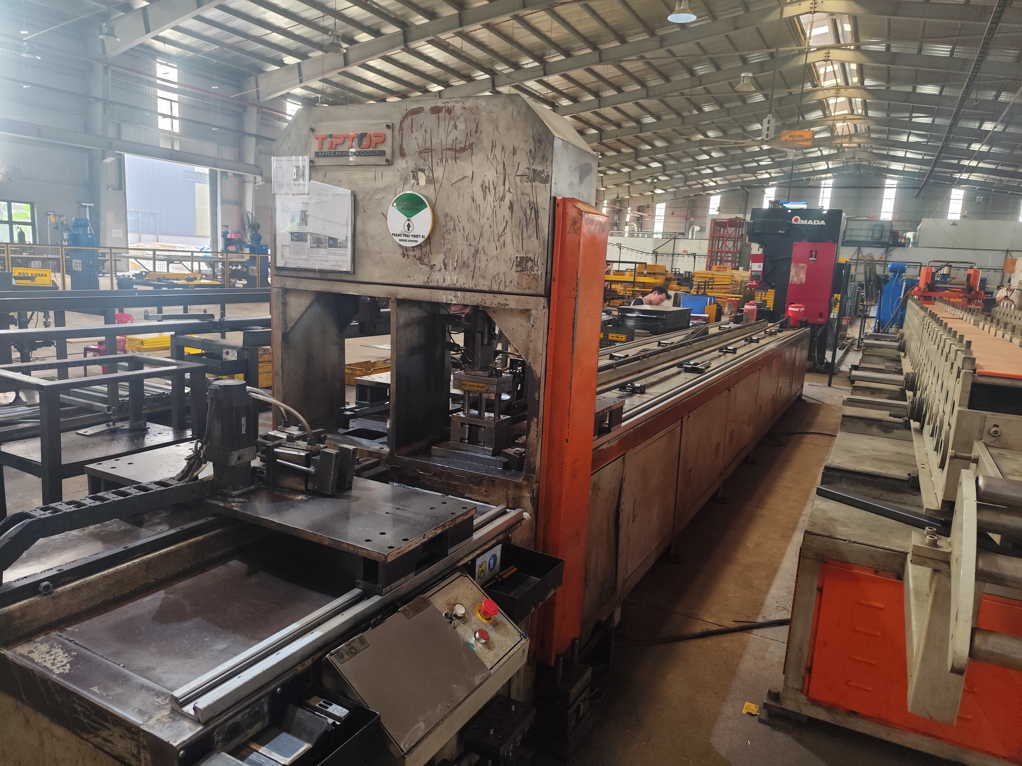
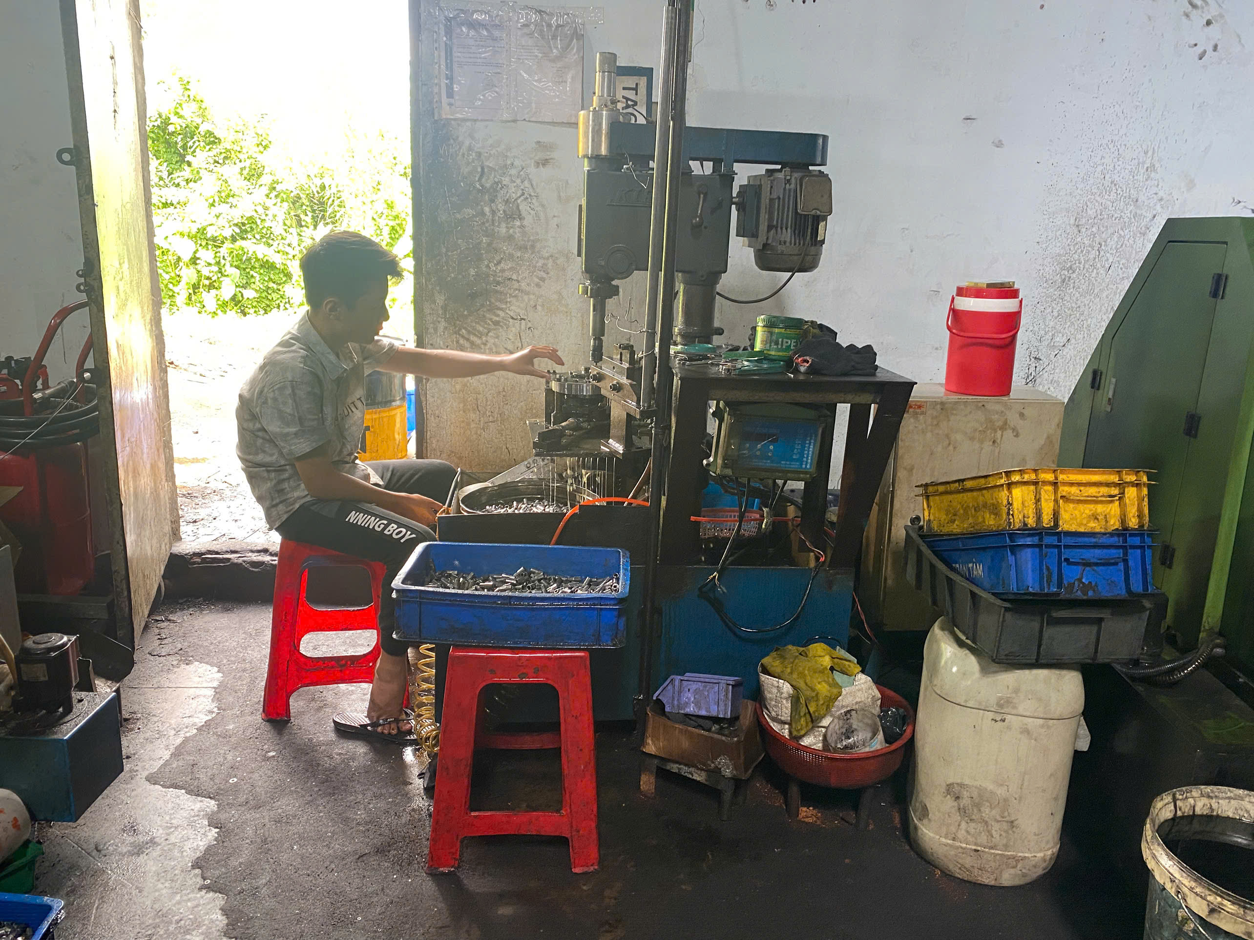
A recurring challenge we face when co-developing custom parts with U.S. buyers is the disconnect between what a design calls for and what fabrication equipment can actually produce—oversized panels that won’t fit a press brake 1, or material thickness choices that push tolerances beyond spec.
Size limits for sheet metal fabrication materials depend on the alloy, material thickness, and fabrication process. Standard sheets range from 48″ × 96″ to 60″ × 120″. Laser cutting supports up to 120″ × 60″, press brake forming up to 80″ in length, and typical sheet metal gauge thickness spans 0.5 mm to 6 mm.
This article breaks down the maximum and minimum dimensions for common materials, explains how equipment and logistics affect what you can order, and shares practical guidelines our team uses to keep large-scale projects on track.
What Are the Maximum Standard Sheet Dimensions I Can Specify for Different Metal Alloys?
One lesson we learned early in our Vietnam facility was that specifying a non-standard sheet size for a simple aluminum enclosure added two weeks to lead time and inflated material cost by nearly 20% sheet metal gauge thickness 2. Standard sheet sizes exist for a reason—they match what mills produce and what fabricators stock.
The maximum standard sheet dimensions vary by alloy: carbon steel and stainless steel are commonly available in 48" × 96", 48" × 120", and 60" × 120" sheets. Aluminum follows similar sizing. Designing within these standard sheet sizes reduces scrap, shortens lead time, and lowers procurement cost significantly.
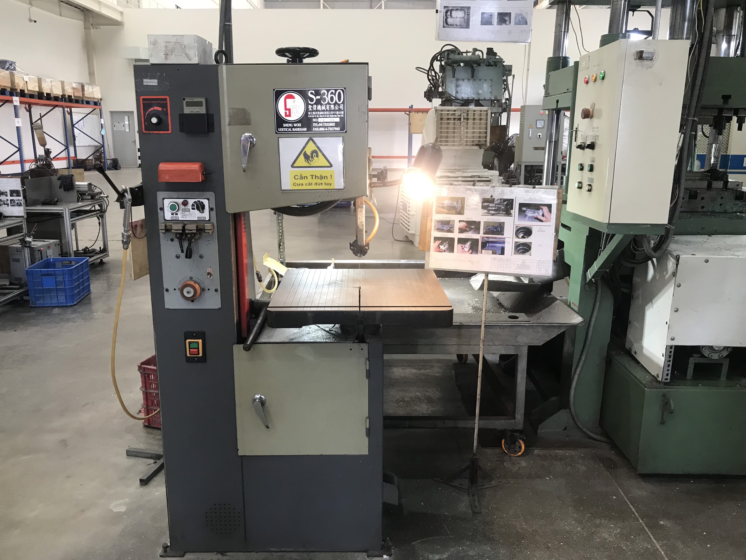
Common Standard Sheet Sizes by Material
Most metal service centers across Asia stock sheets in a handful of standard dimensions Standard sheet dimensions 3. When our sourcing team audits suppliers in Vietnam or China, we always confirm available stock sizes before locking in a design. Here is a quick reference:
| Material | Common Standard Sizes (inches) | Common Standard Sizes (mm) |
|---|---|---|
| Carbon Steel | 48 × 96, 48 × 120, 60 × 120 | 1,219 × 2,438 / 1,219 × 3,048 / 1,524 × 3,048 |
| Stainless Steel | 48 × 96, 48 × 120, 60 × 120 | 1,219 × 2,438 / 1,219 × 3,048 / 1,524 × 3,048 |
| Aluminum | 48 × 96, 48 × 120, 60 × 144 | 1,219 × 2,438 / 1,219 × 3,048 / 1,524 × 3,658 |
| Galvanized Steel | 48 × 96, 48 × 120 | 1,219 × 2,438 / 1,219 × 3,048 |
Aluminum sheets sometimes come in slightly longer lengths—up to 60" × 144"—because aluminum is lighter and easier to handle during coil slitting 20-foot containers 4. Galvanized steel, on the other hand, tends to max out at 48" × 120" in standard coil-cut sheets.
The Gauge System Is Not Universal
A critical detail many purchasing managers overlook is that a specific sheet metal gauge number represents different actual thicknesses depending on the material. A 16-gauge carbon steel sheet is about 1.52 mm thick, but a 16-gauge aluminum sheet is approximately 1.29 mm. This discrepancy directly affects material properties like strength and formability. We always ask our clients to specify dimensions in millimeters or inches rather than gauge numbers to avoid confusion during supplier quoting. For a deeper dive into this topic, see our guide on standard sheet metal thickness ranges for fabrication.
Thickness Ranges: Sheet vs. Plate
The industry generally defines sheet metal as material between 0.5 mm and 6 mm thick. Anything thinner is foil; anything thicker is plate metal thickness territory. Some advanced fabrication shops handle up to 20 mm, but at that point tooling requirements, bend radius 5 constraints, and costs change dramatically. For most custom bracket, housing, and panel projects we manage, the sweet spot is 0.8 mm to 3 mm for aluminum sheet thickness and 1.0 mm to 4 mm for stainless steel dimensions.
| Classification | Thickness Range | Typical Applications |
|---|---|---|
| Foil | < 0.5 mm | Shielding, packaging, thermal insulation |
| Sheet Metal | 0.5 mm – 6 mm | Brackets, enclosures, panels, housings |
| Plate | > 6 mm (up to 20 mm+) | Structural frames, heavy equipment, base plates |
When a design crosses the 6 mm threshold, we flag it during our DFM review. Bend radius must increase to at least 2× material thickness for high-strength or thick materials, and not every press brake in our supplier network can handle it. This is exactly the kind of detail that, if missed, leads to non-conforming parts and costly rework—the number-one pain point we hear from U.S. buyers.
How Do Your Fabrication Equipment Capacities Limit the Overall Size of My Custom Sheet Metal Parts?
During a recent project for mounting brackets destined for a U.S. industrial equipment manufacturer, our supplier's press brake capacity became the bottleneck. The bracket design called for an 85-inch bend—five inches beyond the machine's 80-inch limit. We had to split the part into two welded sections. That single oversight in the initial design added cost and assembly time.
Fabrication equipment sets hard size limits: laser cutting typically handles parts up to 120" × 60" (3,048 mm × 1,524 mm), while press brake capacity usually maxes out at 80" (2,032 mm) bend length. Flat parts can be as small as 0.250" × 0.250", and formed parts start at 0.500" × 0.500".
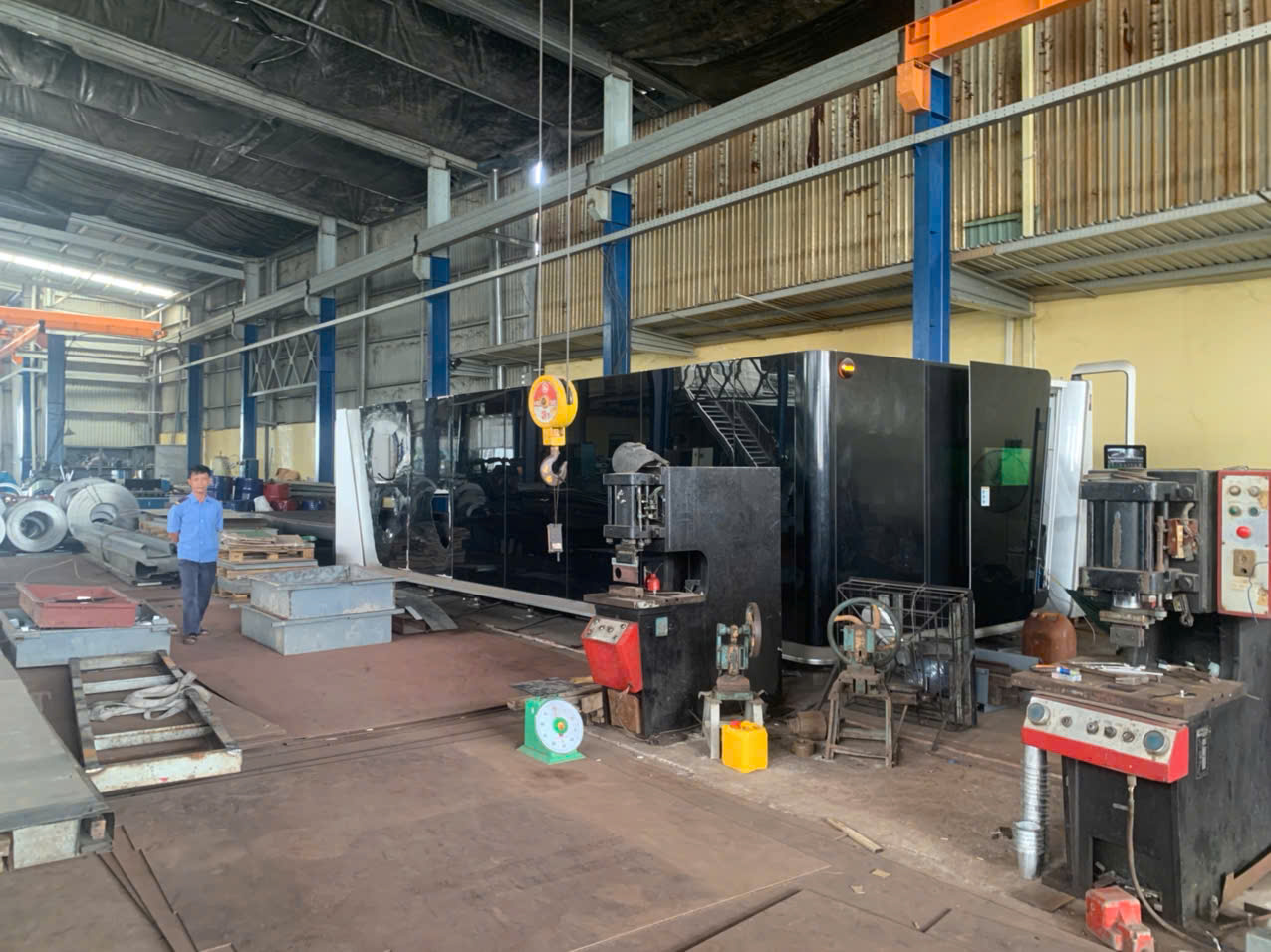
Process-Specific Size Capabilities
Each fabrication process has its own envelope. When we conduct supplier audits across Vietnam and China, we document these limits for every machine on the shop floor. Here is what we commonly find:
| Process | Minimum Part Size | Maximum Part Size | Notes |
|---|---|---|---|
| Laser Cutting 6 | 6.35 mm × 6.35 mm (flat) | 3,048 mm × 1,524 mm (120" × 60") | Laser cutting limits vary by machine bed size |
| CNC Punching | 6.35 mm × 6.35 mm | 1,250 mm × 2,500 mm (typical) | Turret punch presses vary widely |
| Press Brake Forming | 12.7 mm × 12.7 mm (formed) | 2,032 mm (80") bend length | Press brake capacity depends on tonnage and die length |
| Roll Forming | Varies | Up to 1,524 mm width | Continuous profiles; length is nearly unlimited |
The universal maximum overall size many fabrication shops advertise—39" × 47" (990.6 mm × 1,193.8 mm)—is a conservative standard that most facilities can reliably handle. Facilities with larger laser beds and heavier press brakes can exceed this, but you should confirm capability before committing to a design. For a comprehensive look at the factors that limit maximum part size in sheet metal fabrication, we have a dedicated guide.
Flat Parts vs. Formed Parts
Flat parts have a smaller minimum size (6.35 mm × 6.35 mm) because they only require cutting. Formed parts need at least 12.7 mm × 12.7 mm because the bending tools require material to grip. The maximum bend length on a standard press brake is 1,193.8 mm (47 inches), though larger machines push this to 80 inches.
Feature Design Constraints
Beyond overall size, individual features on your part also have limits dictated by the tooling. These rules come from design for manufacturability principles 7, and our engineering team reviews every drawing against them before we release to production:
- Hole diameter: Must be ≥ material thickness. Some shops accept ≥ ½ thickness, but we recommend the full-thickness rule to avoid punch breakage and distortion.
- Notch width: Must be ≥ 1.5× material thickness, and notch length should not exceed 5× the width.
- Tab width: Must be ≥ 2× material thickness or 3.2 mm (whichever is greater), with length ≤ 5× width.
- Bend radius: The minimum inside bend radius equals the material thickness for soft alloys. For high-strength or thick materials above 6 mm, use ≥ 2× thickness.
These are not arbitrary rules. They protect tooling, prevent cracks during forming, and ensure repeatability across production runs. When we catch violations during our DFM review, we propose alternatives to our clients before production begins—this is how we deliver "right first time" results.
The Role of Robotic Automation
An emerging trend we observe in our supplier network is the increasing adoption of robotic automation for material handling. Robots can position and flip large, heavy sheet metal blanks that human operators cannot safely manage. This effectively expands the practical size and weight limits a shop can handle, while also improving consistency. Several of our vetted suppliers in China have added robotic press brake tending cells in the last two years, and this has allowed them to reliably produce larger formed parts with fewer quality escapes.
Will Shipping and Logistics Constraints from Asia Impact the Maximum Size of the Components I Can Order?
A trade-off we weigh on nearly every large-panel order is whether the part should ship flat and be formed domestically, or be fully fabricated in Asia and shipped as a finished assembly. Last year, a protective housing project taught us that a fully welded 1,400 mm × 900 mm × 600 mm enclosure fit inside a standard 20-foot container with room to spare—but a 2,500 mm flat panel required special packaging to prevent bending during transit.
Yes, shipping and logistics from Asia constrain maximum component size. Standard 20-foot containers have internal dimensions of approximately 5,898 mm × 2,352 mm × 2,393 mm. Oversized parts require flat-rack or open-top containers, which cost significantly more and have longer booking lead times, directly impacting project timelines and budgets.
Container Internal Dimensions
Understanding container dimensions is essential when designing large sheet metal parts for international shipment. Here is a comparison:
| Container Type | Internal Length (mm) | Internal Width (mm) | Internal Height (mm) | Best For |
|---|---|---|---|---|
| 20-ft Standard | 5,898 | 2,352 | 2,393 | Most brackets, housings, panels |
| 40-ft Standard | 12,032 | 2,352 | 2,393 | Long panels, large assemblies |
| 40-ft High Cube | 12,032 | 2,352 | 2,698 | Tall enclosures, stacked pallets |
| 20-ft Flat Rack | 5,662 | 2,438 | 2,327 | Oversized or oddly shaped items |
For the vast majority of custom sheet metal parts, a standard 20-foot or 40-foot container provides ample space. Problems arise when parts exceed about 2,300 mm in any single dimension after packaging. Crating, foam padding, and pallet structure all add to the effective footprint.
Practical Packaging Considerations
Our logistics team in Vietnam and China manages door-to-door delivery, so we factor in packaging design early. Thin sheet metal parts—especially large flat panels—are prone to warping, denting, and edge damage during ocean freight. We use interleaving with protective film, custom wooden crates, and anti-vibration foam to keep parts within manufacturing tolerances upon arrival.
For very large components, we sometimes recommend shipping parts in a knocked-down (KD) or semi-finished state and completing final assembly or forming in the U.S. This approach reduces shipping cost, lowers damage risk, and can sometimes sidestep the need for flat-rack containers entirely.
Weight Limits Matter Too
A 20-foot container has a maximum payload of roughly 28,000 kg. Dense materials like stainless steel add up fast. A single pallet of 3 mm stainless steel panels (1,219 mm × 2,438 mm) can weigh over 500 kg. We always run a weight estimate alongside a volume estimate during the quoting phase to avoid surprises at the port.
Emerging trends in sustainable manufacturing also push us toward optimizing nesting layouts to reduce scrap. Less scrap means fewer raw sheets purchased and less weight shipped—a win for cost and environmental impact within a circular economy framework.
How Can I Ensure My Large-Scale Sheet Metal Designs Remain Within Tolerance and Meet Strict Quality Standards?
When we onboarded a new electronics enclosure project last year, the client's drawings specified ±0.127 mm on hole positions and ±0.508 mm on formed dimensions. These are tight but achievable tolerances—if the right process controls are in place. The challenge was not the fabrication itself. It was ensuring that every single part across a 2,000-piece run met spec without rework.
To ensure large-scale sheet metal parts meet tolerance and quality standards, apply DFM principles during design, specify realistic manufacturing tolerances (±0.508 mm for bends, ±0.127 mm for holes, ±1° for angles), implement in-process inspection with calibrated instruments, and use PPAP documentation to validate production readiness before full runs.
Tolerance Ranges by Feature Type
Tolerances vary based on the feature, the material properties, and the fabrication method. Here is what we use as baseline guidance across our supplier network. For a more detailed breakdown, refer to our article on standard precision and tolerance ranges for sheet metal fabrication:
| Feature | Typical Tolerance | Notes |
|---|---|---|
| Hole position / diameter | ±0.127 mm (±0.005") | Achievable with CNC laser or punch |
| Bend angle | ±1° | Springback compensation is critical |
| Formed / bent dimensions | ±0.508 mm (±0.020") | Increases with part size and material thickness |
| Overall flat dimensions | ±0.254 mm (±0.010") | Laser cutting delivers tightest results |
| Edge-to-hole distance | ±0.254 mm (±0.010") | Must account for material stretch near bends |
These values represent what a well-equipped, well-controlled shop can deliver. For tighter tolerances, secondary machining operations may be needed, which adds cost. We always discuss tolerance requirements with our clients during the co-development phase so there are no surprises.
The DFM Review Process
Design for manufacturability is not just a buzzword in our workflow. It is a formal gate. Before any drawing goes to production, our engineering team checks:
- Are all features (holes, notches, tabs) within the minimum size rules for the specified material thickness?
- Is the bend radius appropriate for the alloy and gauge?
- Does the overall part size fit within the selected supplier's laser cutting limits and press brake capacity?
- Are tolerances realistic for the chosen process, or do they require secondary operations?
- Can the part nest efficiently on a standard sheet to minimize waste?
This review catches roughly 60–70% of potential quality issues before metal is ever cut. It is the single most effective tool we have for achieving "right first time" production.
PPAP and In-Process Controls
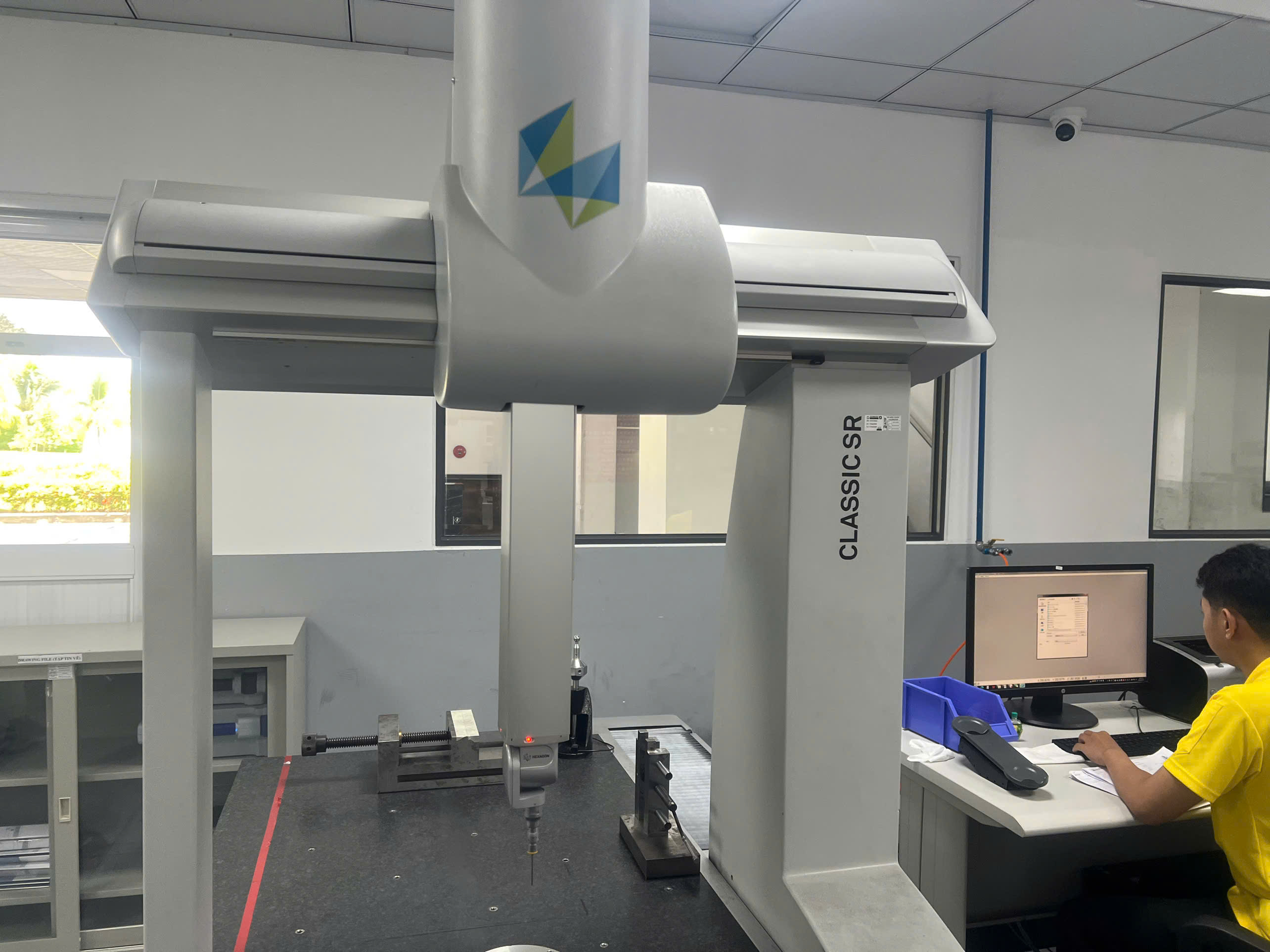
For our U.S. clients, we offer PPAP (Production Part Approval Process) 8 documentation as standard on critical programs. This includes dimensional inspection reports, material certifications, process flow diagrams, and control plans. During production, our QC inspectors perform first-article inspection, in-process sampling, and final inspection using calibrated CMM, calipers, gauges, and optical comparators.
Advanced Finite Element Analysis software 9 also plays a growing role. Several of our engineering partners use FEA to simulate bending and springback behavior before cutting a single sheet. This is especially valuable for large panels or thick materials where trial-and-error would be expensive and time-consuming.
Material-Specific Considerations
Different alloys behave differently under stress. Aluminum is softer and more forgiving during bending, but it scratches easily and requires careful handling. Stainless steel work-hardens quickly, so bend radius must be more generous—often 1.5× to 2× material thickness. Galvanized steel has a zinc coating that can crack at tight bends, so we advise a minimum bend radius of 1× thickness plus the coating thickness. These material properties directly influence what tolerances are achievable at scale.
We have found that clear, proactive communication about these nuances—ideally before the purchase order is issued—eliminates the back-and-forth that causes delivery delays. This is exactly the kind of professional expertise and responsiveness our clients tell us they value most.
Conclusion
Understanding size limits for sheet metal fabrication materials 10—from standard sheet sizes and equipment capacities to shipping constraints and tolerance management—helps you design smarter, avoid costly mistakes, and get parts right the first time.
Frequently Asked Questions
What Are the Maximum Standard Sheet Dimensions I Can Specify for Different Metal Alloys?
One lesson we learned early in our Vietnam facility was that specifying a non-standard sheet size for a simple aluminum enclosure added two weeks to lead time and inflated material cost by nearly 20% sheet metal gauge thickness 2 . Standard sheet sizes exist for a reason—they match what mills produce and what fabricators stock.
How Do Your Fabrication Equipment Capacities Limit the Overall Size of My Custom Sheet Metal Parts?
During a recent project for mounting brackets destined for a U.S. industrial equipment manufacturer, our supplier's press brake capacity became the bottleneck. The bracket design called for an 85-inch bend—five inches beyond the machine's 80-inch limit. We had to split the part into two welded sections. That single oversight in the initial design added cost and assembly time.
Will Shipping and Logistics Constraints from Asia Impact the Maximum Size of the Components I Can Order?
A trade-off we weigh on nearly every large-panel order is whether the part should ship flat and be formed domestically, or be fully fabricated in Asia and shipped as a finished assembly. Last year, a protective housing project taught us that a fully welded 1,400 mm × 900 mm × 600 mm enclosure fit inside a standard 20-foot container with room to spare—but a 2,500 mm flat panel required special packaging to prevent bending during transit.
Footnotes
1. Explains what a press brake is and its function in bending sheet metal. ↩︎
2. Provides an explanation of the gauge system for sheet metal thickness. ↩︎
3. Discusses common standard sheet metal sizes in terms of length and width. ↩︎
4. Offers detailed internal dimensions and capacity information for standard 20-foot shipping containers. ↩︎
5. Defines bend radius and its critical role in sheet metal forming to prevent damage. ↩︎
6. Authoritative source explaining the laser cutting process. ↩︎
7. Explains the core concepts and importance of Design for Manufacturability (DFM). ↩︎
8. Authoritative and comprehensive explanation of the Production Part Approval Process. ↩︎
9. Explains what FEA software is and its applications in engineering simulation. ↩︎
10. Provides an overview of common materials used in sheet metal fabrication. ↩︎