Every week, our engineering team reviews drawings where tolerance callouts either miss the mark or go overboard — both problems cost real money and delay projects.
Standard precision and tolerance ranges for sheet metal fabrication typically fall between ±0.020″ and ±0.030″ (±0.50–0.76 mm) for general features, while high-precision processes like laser cutting can achieve dimensional tolerance as tight as ±0.005″ to ±0.010″ (±0.13–0.25 mm), depending on material type, thickness, and fabrication method.
Getting tolerances right is the difference between parts that fit on the first try and parts that go straight to the scrap bin. Below, we break down exactly how to think about precision for your next sheet metal project — process by process, feature by feature.
How do I determine if standard ISO tolerances are sufficient for my custom sheet metal project?
A U.S. client recently sent us a drawing with every single dimension toleranced to ±0.05 mm. Their previous supplier had delivered out-of-spec parts, so they tightened everything. The result? A 40% cost increase with zero functional improvement.
ISO 2768 standard tolerances — typically ±0.20 mm to ±0.50 mm for linear dimensions — are sufficient for most custom sheet metal projects where parts do not have critical mating interfaces, and applying them as your baseline reduces cost while maintaining acceptable fit and function.

Understanding ISO 2768 Tolerance Classes
ISO 2768 defines four tolerance classes for linear dimensions: fine (f), medium (m), coarse (c), and very coarse (v). ISO 2768 standard tolerances 1 Most sheet metal shops default to the "medium" class when no specific callout is given. This standard simplifies engineering drawings. You do not need to tolerance every single dimension individually. Instead, you reference ISO 2768-m in your title block, and the shop applies the corresponding values based on nominal dimension ranges.
Here is a quick reference for ISO 2768 linear tolerances:
| Nominal Dimension Range | Fine (f) | Medium (m) | Coarse (c) | Very Coarse (v) |
|---|---|---|---|---|
| 0.5 mm – 3 mm | ±0.05 mm | ±0.10 mm | ±0.15 mm | — |
| 3 mm – 6 mm | ±0.05 mm | ±0.10 mm | ±0.20 mm | ±0.50 mm |
| 6 mm – 30 mm | ±0.10 mm | ±0.20 mm | ±0.50 mm | ±1.00 mm |
| 30 mm – 120 mm | ±0.15 mm | ±0.30 mm | ±0.80 mm | ±1.50 mm |
| 120 mm – 400 mm | ±0.20 mm | ±0.50 mm | ±1.20 mm | ±2.50 mm |
When ISO 2768 Medium Is Enough
For most enclosures, brackets, chassis, and non-mating structural components, ISO 2768-m works perfectly. In our experience managing fabrication projects across Vietnam and other Asian suppliers, roughly 70–80% of parts we process require nothing tighter than the medium class. The key question to ask yourself: does this feature mate with another part at a critical interface? If the answer is no, standard tolerances are fine.
When You Need to Go Tighter
You should specify tighter tolerances only on features that directly affect assembly fit. Think press-fit hardware holes, alignment pin locations, or mating flanges. On these features, call out specific dimensional tolerance 2 values — ±0.10 mm or ±0.05 mm — and leave everything else at ISO 2768-m. This targeted approach keeps costs down and communicates your priorities clearly to the shop floor.
One more consideration: angular tolerance 3 under ISO 2768 defaults to ±1° for short sides. If your bending application needs ±0.5°, you must call it out explicitly. Do not assume the supplier will guess.
How can I ensure my overseas supplier maintains consistent precision across high-volume production runs?
Last year, we managed a production run of 5,000 mounting brackets for a U.S. distributor. The first 200 pieces were flawless. By piece 3,000, the bend angles had drifted by 1.5°. The root cause? Tooling wear that went unmonitored.
To maintain consistent precision across high-volume runs from an overseas supplier, you need a structured process control plan that includes first article inspection (PPAP), in-process dimensional checks at defined intervals, statistical process control (SPC) tracking, and final inspection with documented reports — not just reliance on the supplier's word.

The Real Problem with High-Volume Consistency
Achieving tight tolerances on a single prototype is relatively easy. Maintaining those tolerances across thousands of pieces is a completely different challenge. Tooling wears down. Material thickness variation between coil batches shifts dimensions. Operators change shifts. Ambient temperature affects laser cutting 4 tolerances and bending springback. Without systematic controls, drift is inevitable.
Building a Process Control Framework
Here is what we implement on every high-volume project:
Step 1 — PPAP (Production Part Approval Process). Before mass production starts, we require the supplier to produce a sample batch and submit dimensional inspection data on every critical feature. first article inspection (PPAP) 5 This becomes the benchmark.
Step 2 — Control Plan. We define which dimensions get checked, how often, and with what equipment. For example, a critical hole-to-hole dimension might get measured every 50 pieces using a CMM, while a non-critical edge dimension gets a caliper check every 200 pieces.
Step 3 — SPC Monitoring. We track Cpk values on critical features. statistical process control (SPC) 6 A Cpk above 1.33 means the process is capable. Below that, we intervene before defects pile up.
Step 4 — Final Inspection. Every shipment gets an AQL-based inspection. We verify flatness tolerance, angular tolerance, hole positions, and overall dimensions against the approved PPAP samples.
Common Failure Points
| Failure Mode | Root Cause | Prevention |
|---|---|---|
| Bend angle drift | Tooling wear, material variation | In-process angle checks every 100 pcs |
| Hole position shift | CNC program drift, fixture looseness | First-off and mid-run CMM checks |
| Flatness out of spec | Residual stress, improper handling | Post-process flatness measurement |
| Material thickness variation | Different coil batches | Incoming material inspection per ASTM |
| Surface finish defects | Worn tooling, contamination | Visual inspection per AQL Level II |
Our team in Vietnam physically visits suppliers during production runs. We do not rely on self-reported data alone. That hands-on presence is what catches problems at piece 3,000 instead of piece 5,000.
The Role of Design for Manufacturability
Before production even starts, we review every drawing for design for manufacturability 7 issues. If a feature will be hard to hold consistently — say, a bend-to-hole dimension on a long flange — we flag it early. Sometimes a small design change, like adding a relief notch or widening a tolerance on a non-critical feature, dramatically improves consistency across a full run. This is where tolerance stack-up analysis 8 becomes critical. When multiple bends and features interact, each individual tolerance compounds. A part with three bends each at ±0.25 mm can see total variation of ±0.75 mm at the final feature. Understanding this stacking effect helps you set realistic expectations.
What factors should I consider when specifying tighter tolerances to avoid unnecessary manufacturing costs?
One trade-off I weigh on almost every project: will this tighter callout actually improve the part's function, or is it just making the drawing look more "engineered"? Nine times out of ten, the answer is the latter.
When specifying tighter tolerances, consider the functional requirement of each feature, the fabrication process capability, material thickness variation, tolerance stack-up across assembled components, and the exponential — not linear — cost increase that tighter specs create, especially below ±0.10 mm.
The Cost Curve Is Exponential
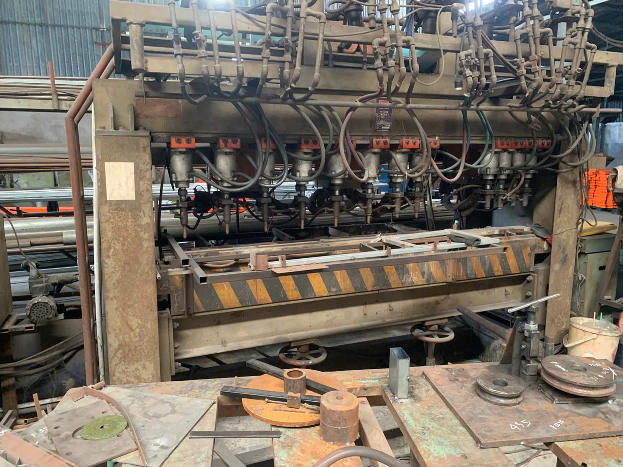
This is the most important concept. Moving from ±0.50 mm to ±0.20 mm might add 5–10% to your part cost. Moving from ±0.20 mm to ±0.10 mm might add another 15–25%. But moving from ±0.10 mm to ±0.05 mm can double or triple the cost. Why? Because at tight tolerances, you need slower machine speeds, more frequent tool changes, 100% inspection instead of sampling, and higher scrap rates. The supplier has to reject more parts that would otherwise be perfectly functional.
A Decision Framework for Tolerance Selection
Ask these four questions before specifying any tolerance tighter than the ISO 2768 medium default:
- Does this feature mate with another part? If yes, calculate the fit requirements using Geometric Dimensioning and Tolerancing principles (ASME Y14.5) 9. If no, leave it at standard.
- What process will produce this feature? Laser cutting tolerances are inherently tighter than bending tolerances. Do not ask a bend to hold ±0.05 mm — it cannot.
- What material and thickness? Thicker materials have more springback and larger material thickness variation from the mill. A 3 mm stainless steel sheet might have ±0.15 mm thickness variation before you even start cutting.
- How many bends or operations are between this feature and the datum? Each operation adds uncertainty. Tolerance stack-up is cumulative.
Feature-Based Tolerance Reference
| Feature Relationship | Standard Tolerance | Precision Tolerance |
|---|---|---|
| Edge to Edge | ±0.13 mm (±0.005") | ±0.08 mm (±0.003") |
| Edge to Hole | ±0.13 mm (±0.005") | ±0.08 mm (±0.003") |
| Hole to Hole | ±0.13 mm (±0.005") | ±0.08 mm (±0.003") |
| Hole to Hardware | ±0.25 mm (±0.010") | ±0.13 mm (±0.005") |
| Bend to Hole | ±0.38 mm (±0.015") | ±0.20 mm (±0.008") |
| Bend to Bend | ±0.38 mm (±0.015") | ±0.25 mm (±0.010") |
| Bend to Edge | ±0.25 mm (±0.010") | ±0.15 mm (±0.006") |
| Angular | ±1.0° | ±0.5° |
| Flatness (per 300 mm) | ±0.76 mm (±0.030") | ±0.38 mm (±0.015") |
Notice the pattern: any feature relationship that involves a bend has a wider tolerance. That is physics, not poor workmanship. Springback, material grain direction, and die condition all affect the outcome.
The "Right First Time" Approach
When we review a new project, our engineers categorize every dimension into three buckets: critical (tight tolerance), important (standard tolerance), and reference (informational only). This exercise typically reduces the number of tight-tolerance callouts by 60% or more. The drawing becomes easier to manufacture, easier to inspect, and the supplier can focus quality efforts where they truly matter. The result is fewer rejects, faster delivery, and lower cost — without sacrificing function.
How do different fabrication processes like laser cutting and CNC bending affect my final part dimensions?
During a recent supplier audit in Vietnam, I watched a fiber laser cut a batch of 2 mm aluminum panels with edge-to-edge accuracy within ±0.08 mm. Then the same panels went to the press brake for bending, and the bend-to-edge dimension varied by ±0.35 mm. Same part, same shop — completely different precision levels depending on the fabrication method.
Different fabrication processes produce vastly different tolerance capabilities: laser cutting holds ±0.005"–0.010" (±0.13–0.25 mm), punching achieves ±0.005"–0.010", CNC bending holds ±1° angular and ±0.25–0.50 mm linear, while welding is the loosest at ±0.25–0.50 mm — making process selection the single biggest factor in your final part dimensions.
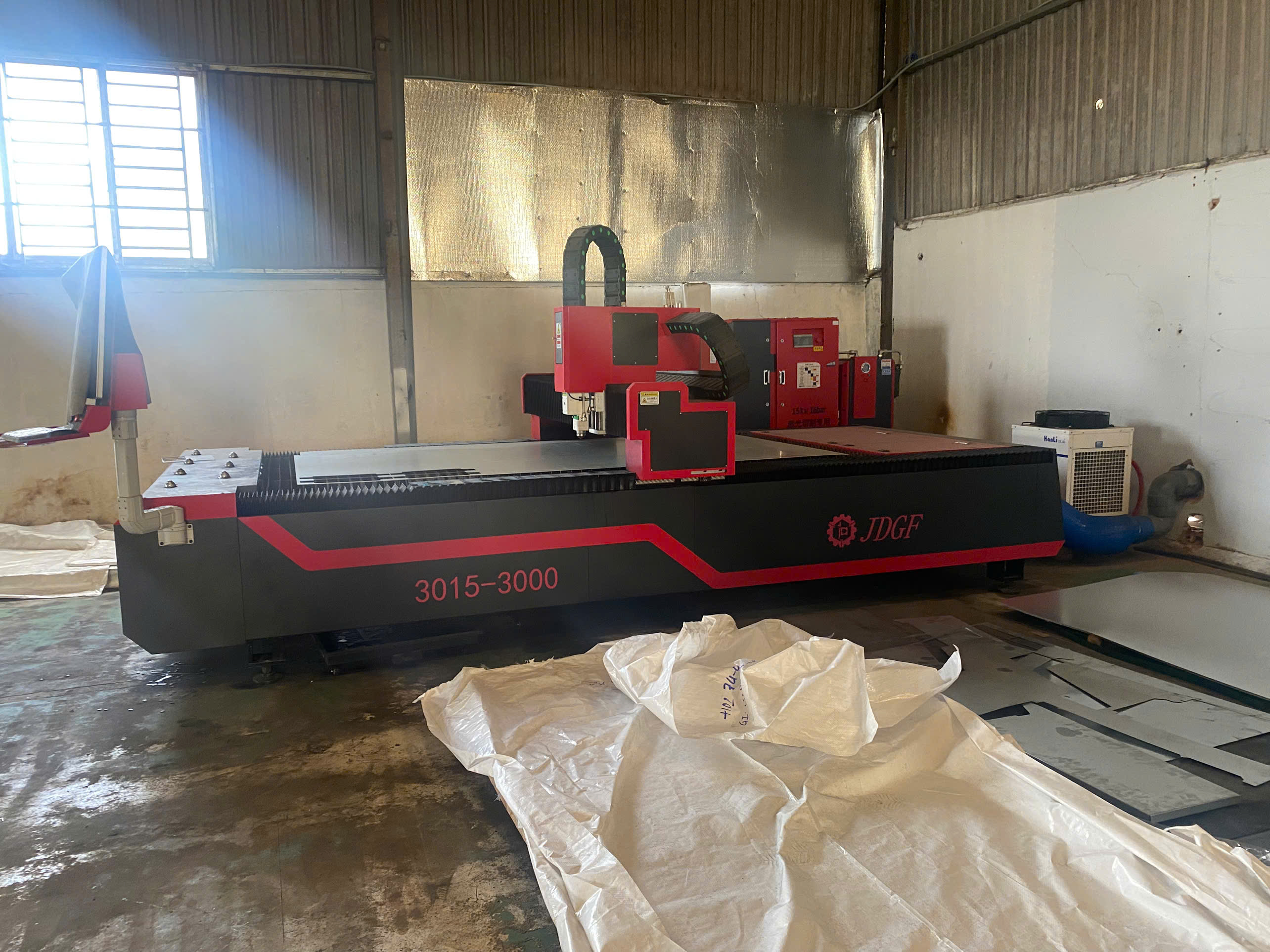
Laser Cutting: The Precision Benchmark
Modern fiber lasers are the gold standard for flat-profile accuracy. They achieve laser cutting tolerances of ±0.10–0.20 mm as standard, with high-end machines reaching ±0.05 mm on thin materials. Hole diameters typically hold ±0.10–0.15 mm. Feature location accuracy sits at ±0.20–0.30 mm.
Key variables that affect laser cutting precision:
- Material thickness. Thinner sheets (under 3 mm) cut more precisely than thick plates.
- Material type. Mild steel cuts cleaner than aluminum, which tends to produce more dross.
- Kerf width. The laser beam removes material. Modern software compensates for this, but it introduces a small variable.
- Thermal distortion. Cutting generates heat. On large, thin sheets, this can cause warping that affects flatness tolerance.
For a deeper comparison of cutting methods and their precision trade-offs, see our article on the differences between laser and plasma cutting for sheet metal fabrication.
CNC Bending: Where Precision Gets Harder
Sheet metal bending introduces the most variability in the entire fabrication chain. The standard angular tolerance for a press brake bend is ±1°. Precision setups with in-process angle measurement can achieve ±0.5°. Linear dimensions related to bends — like flange length — typically vary by ±0.25–0.50 mm.
Why is bending less precise? Three main reasons:
- Springback. Every material springs back after bending. The amount depends on material type, thickness, hardness, and grain direction. Springback must be compensated for in the tooling setup, and it is never perfectly predictable.
- Material thickness variation. A sheet specified at 2.0 mm might actually be 1.92 mm or 2.08 mm due to mill tolerance. That difference changes the bend angle.
- Inside bend radius. The die opening and punch tip radius affect the final bend geometry. Thicker materials require larger radii, which increases dimensional variation on flange lengths.
For more detail on how these variables interact, our guide on the key technical points of bending in sheet metal fabrication covers springback compensation and tooling selection in depth.
Punching and Stamping
CNC turret punching holds tolerances similar to laser cutting — ±0.13–0.25 mm for hole positions and profiles. Stamping in dedicated dies can be even tighter, but the tooling cost is only justified at very high volumes (typically 10,000+ pieces). For most custom and mid-volume projects, laser cutting has largely replaced punching for profile work.
Welding and Assembly
Welding is inherently the loosest process. Heat input causes distortion. Even skilled welders with fixtures and jigs produce assemblies with ±0.25–0.50 mm variation on weldment dimensions. For welded assemblies requiring tight final dimensions, post-weld machining is often necessary. Understanding the common welding processes in sheet metal fabrication can help you choose a method that minimizes distortion for your specific application.
Process Capability Summary
| Process | Typical Tolerance (mm) | Typical Tolerance (inches) | Best For |
|---|---|---|---|
| Fiber Laser Cutting | ±0.10 – 0.20 | ±0.004 – 0.008 | Flat profiles, holes, slots |
| CNC Punching | ±0.13 – 0.25 | ±0.005 – 0.010 | Holes, louvers, simple profiles |
| CNC Bending (linear) | ±0.25 – 0.50 | ±0.010 – 0.020 | Flanges, channels, enclosures |
| CNC Bending (angular) | ±0.5° – 1.0° | ±0.5° – 1.0° | All bend features |
| Welding | ±0.25 – 0.50 | ±0.010 – 0.020 | Joining, structural assemblies |
| Post-weld Machining | ±0.05 – 0.10 | ±0.002 – 0.004 | Critical mating surfaces |
Practical Implications for Your Drawings
When you design a sheet metal part, think about the fabrication sequence. Features created in the flat state (before bending) inherit the precision of the laser or punch. Features whose position depends on a bend inherit the lower precision of the press brake. This is why bend-to-hole tolerances are always wider than hole-to-hole tolerances.
If you need a tight relationship between a hole and a bent flange, consider adding the hole after bending using a secondary machining operation. It costs more, but it eliminates the bend-to-hole stack-up entirely. This is a classic design for manufacturability decision — trading a small process cost for a big precision gain where it matters.
Conclusion
Standard sheet metal fabrication 10 tolerances range from ±0.005" to ±0.030" depending on feature type and process. Specify tight tolerances only where function demands it, and partner with a supplier who understands process control, tolerance stack-up, and design for manufacturability.
Frequently Asked Questions
How do I determine if standard ISO tolerances are sufficient for my custom sheet metal project?
A U.S. client recently sent us a drawing with every single dimension toleranced to ±0.05 mm. Their previous supplier had delivered out-of-spec parts, so they tightened everything. The result? A 40% cost increase with zero functional improvement.
How can I ensure my overseas supplier maintains consistent precision across high-volume production runs?
Last year, we managed a production run of 5,000 mounting brackets for a U.S. distributor. The first 200 pieces were flawless. By piece 3,000, the bend angles had drifted by 1.5°. The root cause? Tooling wear that went unmonitored.
What factors should I consider when specifying tighter tolerances to avoid unnecessary manufacturing costs?
One trade-off I weigh on almost every project: will this tighter callout actually improve the part's function, or is it just making the drawing look more "engineered"? Nine times out of ten, the answer is the latter.
Footnotes
1. Replaced HTTP 404 with a working Wikipedia page, an authoritative source for ISO standards. ↩︎
2. Defines dimensional tolerance and its importance in manufacturing and measurement. ↩︎
3. Defines angular tolerance and its importance in engineering and manufacturing. ↩︎
4. Replaced HTTP 404 with a working URL from an authoritative engineering and technology organization. ↩︎
5. Explains First Article Inspection (FAI) and its role within the PPAP process. ↩︎
6. Provides a comprehensive definition and tools for statistical process control. ↩︎
7. Explains the principles and benefits of Design for Manufacturability (DFM). ↩︎
8. Details the process and methods for performing tolerance stack-up analysis. ↩︎
9. Provides the authoritative standard for Geometric Dimensioning and Tolerancing (GD&T). ↩︎
10. Provides a comprehensive guide to sheet metal fabrication processes and materials. ↩︎