
Surface roughness standards for sheet metal fabrication confused one of our U.S. clients so badly that his first batch of brackets failed assembly — the mating surfaces were too rough, and the seals leaked under pressure.
Surface roughness standards for sheet metal fabrication typically default to 6.3 µm Ra (250 µin) for non-mating clearance surfaces and 3.2 µm Ra (125 µin) or finer for functional mating surfaces, governed by ASME B46.1 and ISO 21920 standards for measurement and specification.
This article breaks down how to pick the right Ra value 1, how each fabrication process affects surface texture, how to verify roughness with offshore suppliers, and what tighter finishes really cost you.
How do I determine the correct Ra value for my custom sheet metal components?
A purchasing manager in Ohio once sent us a drawing with no surface finish callout at all — just a note saying "smooth." That single word triggered three rounds of back-and-forth before we aligned on a measurable target ISO 21920 standards 2.
To determine the correct Ra value, identify each surface's function first: use 6.3 µm Ra for clearance faces, 3.2 µm Ra for structural mating surfaces, 1.6 µm Ra for O-ring grooves, and 0.4 µm Ra for high-pressure seals, then mark these on your engineering drawings.
Start With Function, Not Aesthetics
The biggest mistake I see from new clients is specifying a mirror finish on parts that bolt together inside an enclosure nobody ever opens. That drives cost up for zero benefit. Instead, walk through each surface on your part and ask: does this face seal against something? Does it slide? Does it need paint adhesion? Or is it just a clearance face?
For clearance surfaces — areas that never touch another part — 6.3 µm Ra is the industry default. It comes straight off most standard sheet metal processes without any secondary finishing. For mating surfaces where two parts press together or a gasket sits, 3.2 µm Ra is the baseline. If you have an O-ring groove 3 or a press-fit bore, step down to 1.6 µm Ra. High-pressure fluid seals demand 0.4 µm Ra or even finer.
Ra Value Selection Guide by Application
| Application | Recommended Ra (µm) | Recommended Ra (µin) | Typical Process |
|---|---|---|---|
| Clearance / non-contact surfaces | 6.3 | 250 | Laser cutting, shearing |
| Structural mating faces | 3.2 | 125 | CNC milling, turning |
| O-ring grooves / press-fits | 1.6 | 63 | Precision machining |
| High-pressure fluid seals | 0.4 | 16 | Fine grinding, lapping |
| Mirror / decorative | 0.2–0.5 | 8–20 | Polishing, grinding |
Ra vs. Grit vs. Source Finish — When to Use Which
Our engineering team in Vietnam often gets drawings that mix Ra callouts with grit numbers on the same part. This creates confusion on the shop floor. Here is the simple rule: use Ra when the surface must perform a measurable function — sealing, sliding, or cleanability. Use grit (e.g., 120 grit, 150 grit) or source finish designations (2B, #4, BA) when the requirement is purely cosmetic, such as a brushed stainless steel panel that faces a customer.
The ASME B46.1 4 standard and the newer ISO 21920 series both define Ra as the arithmetic average of peaks and valleys measured over a sampling length. Rz, or maximum height, captures the difference between the tallest peak and the deepest valley and is more useful for sealing applications where a single deep scratch can cause a leak. Both parameters can be measured with a profilometer or laser scanner 5, and both should appear on your engineering drawings 6 when function demands it.
A practical tip from our experience: define a "Side A" (cosmetic, visible) and "Side B" (hidden) on your drawings. This lets the fabricator focus finishing effort where it matters and skip costly polishing on hidden faces. It is one of the simplest cost-saving moves we recommend to U.S. clients importing custom brackets and enclosures.
How will the choice of fabrication process affect the final surface finish of my parts?
Last quarter, a client asked us to quote the same mounting bracket in both laser-cut and CNC-milled versions. The price difference was modest, but the surface texture gap was significant — and that gap determined whether his downstream powder coat would adhere properly.
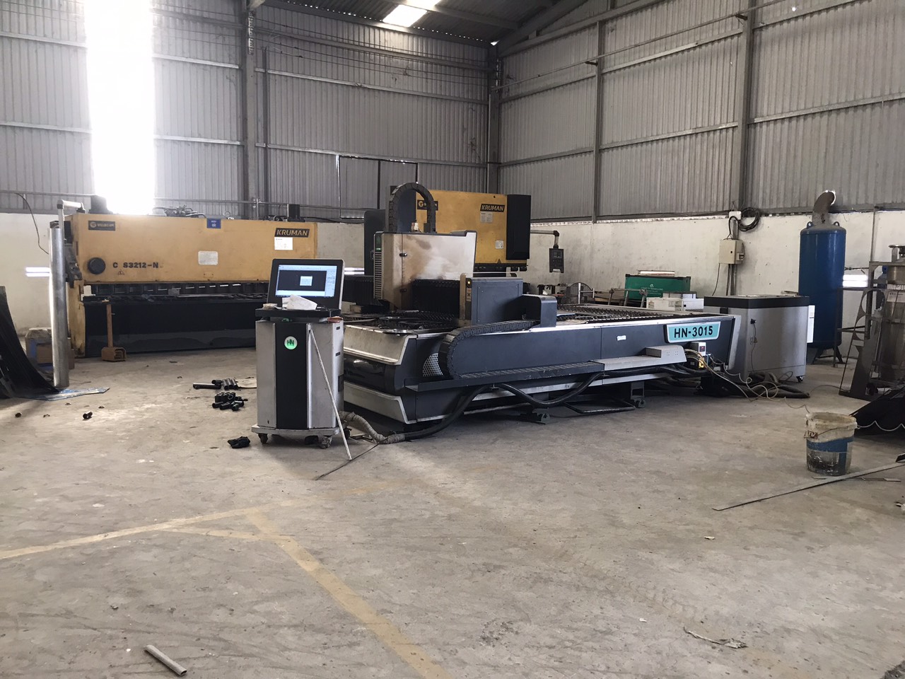
Each fabrication process produces a distinct surface roughness range: laser cutting yields 6.3–12.5 µm Ra, CNC milling achieves 3.2 µm Ra baseline, grinding reaches 0.2 µm Ra, EDM falls between 1.6–6.3 µm Ra, and 3D printing varies widely from 3.2–25 µm Ra.
Process-by-Process Roughness Breakdown
Understanding what each process can deliver "as-machined" saves you from specifying a finish that requires expensive secondary operations. Here is a surface finish chart organized by process:
| Fabrication Process | Typical Ra Range (µm) | Typical Ra Range (µin) | Post-Processing Needed? |
|---|---|---|---|
| Laser Cutting | 6.3–12.5 | 250–500 | Usually no, for structural parts |
| CNC Milling / Turning | 3.2 | 125 | No, for mating faces |
| Precision Machining | 0.4–1.6 | 16–63 | Minimal, for seals and fits |
| Grinding | 0.2 | 8 | No, delivers fine finish directly |
| EDM (Electrical Discharge) | 1.6–6.3 | 63–250 | Sometimes, depending on application |
| 3D Printing 7 | 3.2–25 | 125–1000 | Almost always |
| Bead Blasting | 1.0–6.0 | 40–240 | It is the post-process itself |
| Bored / Turned | 0.4–6.0 | 16–240 | Depends on tolerance class |
Why Laser Cutting Is Often "Good Enough"
For structural components — brackets, gussets, mounting plates — laser-cut edges at 6.3–12.5 µm Ra are perfectly acceptable. Many of our clients shipping to U.S. distributors use laser-cut parts directly in assemblies where the edge is hidden or non-functional. This eliminates a secondary grinding step and shaves days off lead times.
However, if that same edge becomes a sealing face or a sliding interface, laser cutting alone will not meet the roughness requirement. You would need to add a milling or grinding operation on that specific face. This is why surface finish callouts should be applied per-surface on your engineering drawings, not as a blanket note across the entire part.
The 3D Printing Wild Card
3D printing introduces the widest variability of any process. The surface texture depends on layer height, material, print orientation, and technology (SLS, DMLS, FDM). A single part can show 3.2 µm Ra on a top face and 25 µm Ra on a side wall. When we handle 3D-printed prototypes for clients, we always discuss which faces need post-processing and which can stay as-printed.
Process Selection and Mechanical Properties
The fabrication process also affects waviness and lay — the broader surface patterns that sit underneath the roughness measurement. A milled surface has a directional lay from the cutter path. A ground surface has a finer, more uniform lay. These patterns influence how coatings adhere, how corrosion resistance 8 performs over time, and how two mating parts behave under load. Choosing the right process up front means fewer surprises at assembly.
How can I ensure my offshore supplier accurately measures and maintains my roughness standards?
One lesson we learned early on when setting up our Vietnam office: a supplier can own a profilometer and still deliver out-of-spec parts if nobody has calibrated the instrument in six months. Verification is not just about having the right tool — it is about the right process behind the tool.
To ensure your offshore supplier maintains roughness standards, require calibrated profilometer readings per ASME B46.1 or ISO 21920, request roughness measurement data in PPAP documentation, conduct periodic supplier audits, and use comparator plates as a quick visual cross-check during inspections.
Step 1: Specify Measurement Method on the Drawing
Your engineering drawings should not just state "Ra 3.2 µm." They should reference the standard (ASME B46.1 or ISO 21920), the sampling length, and the measurement direction relative to the lay. Without these details, two different profilometers can return different numbers on the same part. Our quality control team in China includes these parameters in every inspection plan we develop for U.S. clients.
Step 2: Require Calibrated Equipment
A profilometer — whether contact-stylus or laser-based — must be calibrated per the manufacturer's schedule. During our supplier audits, we check calibration stickers and certificates. If the last calibration was more than 12 months ago, we flag it. This is a basic step, but it catches a surprising number of issues.
Step 3: Build Roughness Into Your PPAP
When we run a PPAP (Production Part Approval Process) for a new custom part, roughness measurement is part of the dimensional report. PPAP documentation 9 We record Ra and, where applicable, Rz values on critical surfaces. This creates a documented baseline the supplier must maintain throughout production. If values drift, we catch it early through our process control checks — not after 5,000 parts land in a U.S. warehouse.
Step 4: Use Comparator Plates for Quick Checks
Rupert comparator plates (also called roughness comparison specimens) cost roughly $20 for a handheld set. They let an inspector press a known-roughness sample against the part surface and compare by touch and sight. These are not a substitute for a profilometer, but they are an excellent first-pass screening tool. Our inspectors in Vietnam carry them on every shop-floor visit.
Emerging Verification Technologies
AI-driven optical inspection systems are beginning to appear in Asian fabrication shops. These systems use cameras and algorithms to evaluate surface texture without contact, catching micro-defects that a stylus might miss. Digital twin technology also lets manufacturers simulate roughness outcomes before cutting metal, reducing trial-and-error. While these tools are not yet universal, they are worth asking about when evaluating a new supplier's capabilities.
Supplier Verification Checklist
| Verification Step | Tool / Document | Frequency |
|---|---|---|
| Drawing roughness callout | Engineering drawing with Ra, standard, sampling length | Every new part / revision |
| Profilometer calibration | Calibration certificate | Annual minimum; verify at audit |
| PPAP roughness data | Dimensional inspection report | First article and major changes |
| Comparator plate screening | Rupert plates or equivalent | Every production lot |
| Supplier audit | On-site visit checklist | Semi-annual or annual |
| AI optical inspection (emerging) | Vision system with micro-texture analysis | Per-part if available |
Will specifying a higher surface finish quality impact my overall production costs and lead times?
A trade-off conversation I have with nearly every new client goes like this: "Can you get me a 0.8 µm finish on all surfaces?" My answer is always the same — yes, but do you need it on all surfaces?
Yes, specifying a higher surface finish (lower Ra) increases both cost and lead time because it requires additional precision operations like grinding or polishing, tighter process controls, and more inspection steps — often adding 15–30% to part cost and several days to production schedules.
Where the Extra Cost Comes From
Smoother surfaces demand slower feed rates, finer tooling, and sometimes entirely separate machines. A part that comes off the laser cutter at 6.3 µm Ra costs X. Getting that same part to 1.6 µm Ra might require CNC milling on the critical face, plus deburring. Getting it to 0.4 µm Ra adds a grinding step. Each operation adds machine time, operator time, and setup time.
Beyond direct machining costs, tighter roughness specs increase inspection burden. Every critical surface needs a profilometer reading, which takes time. Reject rates also climb because the precision and tolerance band is narrower. A part that passes at 6.3 µm Ra might fail at 1.6 µm Ra due to a single tool mark.
Cost-Saving Strategies That Work
Over years of helping U.S. clients source custom parts from Asia, we have seen several strategies consistently reduce costs without sacrificing quality:
-
Define Side A / Side B. If only one face is visible, specify your cosmetic finish only on that side. The hidden side can stay at the standard process finish.
-
Use grit finish for cosmetics, Ra for function. Brushed stainless panels look great with a 150-grit finish specification. Reserve Ra callouts for surfaces where sealing or mechanical properties actually matter.
-
Avoid over-specification. A 6.3 µm Ra surface is fine for 80% of sheet metal fabrication applications. Only step down to 3.2 µm or finer where function demands it.
-
Specify grain direction on brushed finishes. A simple arrow on the drawing prevents the fabricator from guessing — and reworking.
-
Consider sustainability. Eco-friendly finishing processes that minimize waste are gaining traction. Some reduce cost by eliminating chemical polishing steps.
Stainless Steel Finish Standards — A Common Reference
Many of our clients work with stainless steel panels and enclosures. The industry uses specific source finish designations that map roughly to grit and Ra values:
| Stainless Steel Finish | Description | Approximate Grit | Approximate Ra (µm) |
|---|---|---|---|
| 2B | Bright, cold rolled | N/A (mill finish) | 0.5–1.0 |
| #3 | Brushed | 120 | 0.8–1.5 |
| #4 | Brushed, finer | 150 | 0.4–1.0 |
| #8 | Mirror | 320+ / polished | < 0.1 |
| BA | Bright annealed | N/A (heat treated) | 0.2–0.5 |
For ISO surface finish compliance on stainless panels, many clients specify the source finish rather than a measured Ra. This is perfectly acceptable for cosmetic applications. But if that panel also has a gasket mating surface, we add a measured Ra callout on that specific zone.
Lead Time Impact
In our experience, adding one finishing operation typically adds one to three working days per batch. Adding two operations — say milling plus polishing — can add a full week. For large orders, this cascades through the schedule. Planning the right finish at the design stage, rather than adding it mid-production, is the single best way to protect your delivery timeline.
Conclusion
Surface roughness standards for sheet metal fabrication come down to matching the Ra value to each surface's function, choosing the right process, verifying with calibrated tools, and avoiding over-specification to control costs and lead times.
Frequently Asked Questions
How do I determine the correct Ra value for my custom sheet metal components?
A purchasing manager in Ohio once sent us a drawing with no surface finish callout at all — just a note saying "smooth." That single word triggered three rounds of back-and-forth before we aligned on a measurable target ISO 21920 standards 2 .
How will the choice of fabrication process affect the final surface finish of my parts?
Last quarter, a client asked us to quote the same mounting bracket in both laser-cut and CNC-milled versions. The price difference was modest, but the surface texture gap was significant — and that gap determined whether his downstream powder coat would adhere properly.
How can I ensure my offshore supplier accurately measures and maintains my roughness standards?
One lesson we learned early on when setting up our Vietnam office: a supplier can own a profilometer and still deliver out-of-spec parts if nobody has calibrated the instrument in six months. Verification is not just about having the right tool — it is about the right process behind the tool.
Footnotes
1. Explains the definition and measurement of average roughness (Ra). ↩︎
2. International standard for surface texture by profile methods. ↩︎
3. Provides guidelines and calculator for O-ring groove and gland dimensions. ↩︎
4. Official standard for surface texture, roughness, waviness, and lay. ↩︎
5. Replaced HTTP 503 with a detailed article explaining profilometers, including optical (laser-based) types. ↩︎
6. Replaced HTTP 405 with a comprehensive guide to engineering drawings. ↩︎
7. Provides an overview of 3D printing processes and technologies. ↩︎
8. Explains what corrosion resistance is and lists common corrosion-resistant materials. ↩︎
9. Outlines the requirements and elements of Production Part Approval Process documentation. ↩︎