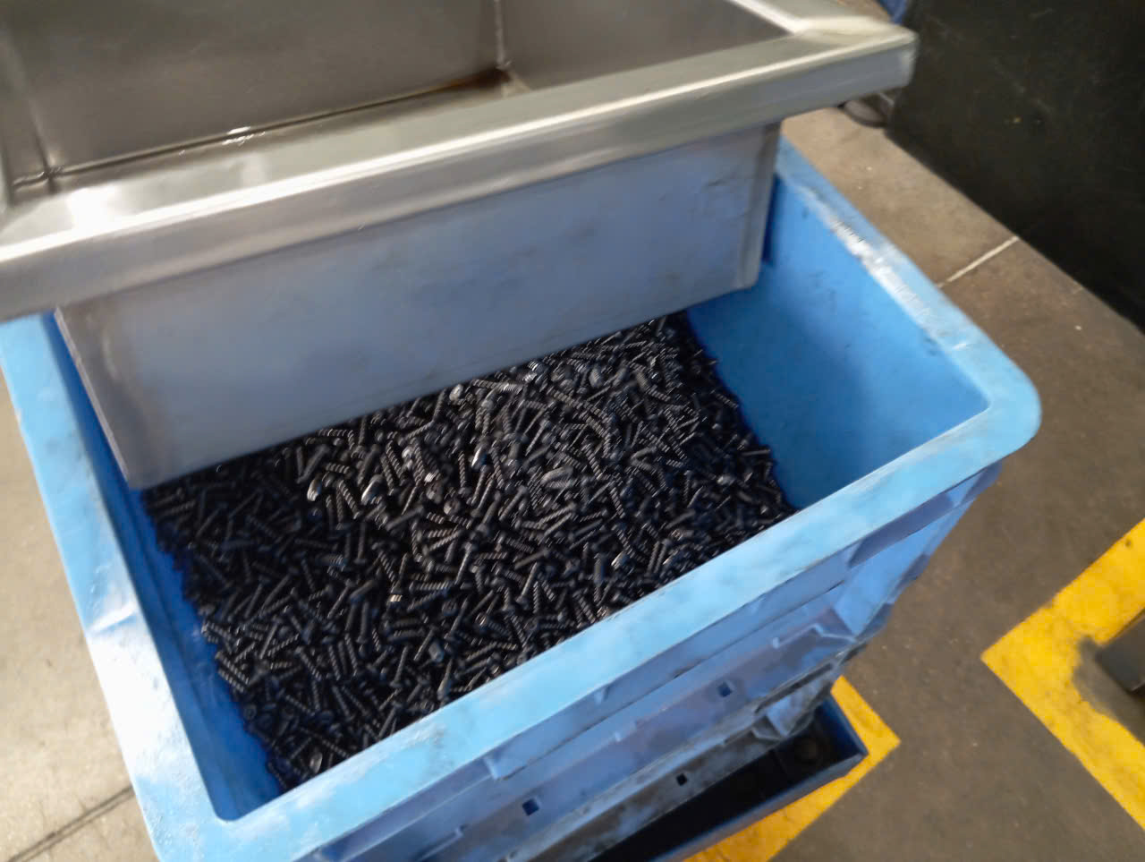

Last year, a U.S. client sent us drawings for a set of mounting brackets in 0.6 mm DP800 steel — and within hours, our engineering team flagged three problems that would have killed the project before first article.
The technical challenges of high-strength steel and ultra-thin stamping center on severe springback, accelerated tooling wear and galling, dimensional instability from wrinkling and splitting, and the need for significantly higher press tonnage — all of which demand specialized equipment, simulation, and process control to overcome.
These challenges are not theoretical. They show up on the shop floor every day, and they directly affect cost, lead time, and part quality. Below, I will walk through the most critical issues and share what our team has learned managing these projects across suppliers in Vietnam, China, and Taiwan World Trade Organization 1.
How Can I Prevent Springback Issues When Stamping High-Strength Steel Parts?
One trade-off we constantly weigh with clients is geometry complexity versus springback risk. A purchasing manager once asked us to hold ±0.1 mm on a Z-shaped bracket in 980 MPa steel — cold stamped. That conversation quickly turned into a lesson on the physics of elastic recovery.
Preventing springback in high-strength steel stamping requires a combination of springback compensation in die design, overbending strategies, optimized blank holder force, and increasingly, the use of servo press technology or press hardening (hot stamping) to reduce elastic recovery after forming.
Why Springback Is Worse in AHSS
Springback happens because the material tries to return to its original shape after the forming load is removed. In mild steel, this elastic recovery is small and predictable. In Advanced High-Strength Steel 2 (AHSS), the yield-to-tensile strength ratio is much higher. The material stores more elastic energy during forming. When you open the die, that energy releases. The part "springs" away from its intended shape.
This is not just a minor annoyance. On structural automotive brackets and electronic mounting clips, springback can push a part out of tolerance entirely. Sidewall curl, twist, and angular change are all common. And because AHSS work-hardens rapidly — requiring roughly 20% higher tonnage than conventional HSLA grades — the stresses locked into the part are even greater.
Practical Approaches We Use
Here is a breakdown of the most effective springback compensation methods we coordinate with our stamping suppliers:
| Method | How It Works | Best For |
|---|---|---|
| Die overbending | The die bends the part past the target angle so it springs back to the correct position | Simple bends, brackets |
| Variable blank holder force | Adjusting clamping pressure during the stroke to control material flow | Deep draws, complex shapes |
| Servo press pulse motion | Servo press technology uses programmable slide motion to manage strain rate and reduce stored stress | Ultra-thin gauges, AHSS |
| Press hardening (hot stamping) | Forming at 900°C+ then quenching in the die eliminates most springback | Ultra-high-strength parts above 1000 MPa |
| Finite Element Analysis 3 (FEA) simulation | Predicting springback digitally and adjusting die geometry before cutting steel | All AHSS parts, especially new designs |
The Role of Simulation
Traditional forming simulation focuses on strain-based failure — will the material crack or thin too much? But for AHSS, the bigger question is stress-based: where will the residual stress cause the part to move after forming? Modern Finite Element Analysis tools can now predict springback with reasonable accuracy, but the simulation must account for the material's complex work hardening behavior and aniso 4tropy.
We always push our suppliers to run FEA on high-strength steel parts before cutting any tooling. It costs time upfront but saves weeks of die rework later — a lesson we learned the hard way on an early project.
What Tolerances Should I Expect When Sourcing Ultra-Thin Stamped Components?
A buyer interaction that comes up regularly: a client sends a drawing with ±0.05 mm flatness on a 0.3 mm stainless steel clip and asks if that is realistic. The honest answer depends entirely on the geometry, the material grade, and the supplier's process control.
For ultra-thin stamped components (under 1.0 mm gauge), typical achievable dimensional tolerances range from ±0.05 mm to ±0.15 mm depending on material type, part complexity, and press capability. Flatness and angular tolerances are harder to hold due to wrinkling, coil set, and residual stress effects.

What Drives Tolerance in Thin-Gauge Stamping
Ultra-thin materials lack structural mass. A 0.4 mm sheet of stainless steel behaves very differently from a 2.0 mm sheet of the same grade. It wrinkles more easily under compression. It is more sensitive to die clearance. And any coil set — the curvature retained from being wound on a coil — is harder to flatten out.
Our suppliers use straightening rolls to remove coil set, but ultra-thin AHSS retains more curvature due to its high yield strength. The coil-feed equipment needs more working rolls, smaller in diameter, backed by larger support rolls. Without this setup, the strip enters the die with built-in distortion that carries through to the finished part.
Tolerance Ranges by Material and Thickness
| Material Gauge | Dimensional Tolerance (Typical) | Flatness Tolerance (Typical) | Angular Tolerance (Typical) |
|---|---|---|---|
| 0.1 – 0.3 mm | ±0.05 to ±0.10 mm | ±0.10 mm over 25 mm | ±1.0° to ±1.5° |
| 0.3 – 0.6 mm | ±0.05 to ±0.10 mm | ±0.08 mm over 25 mm | ±0.5° to ±1.0° |
| 0.6 – 1.0 mm | ±0.05 to ±0.15 mm | ±0.05 mm over 25 mm | ±0.5° |
| 1.0 – 2.0 mm (reference) | ±0.10 to ±0.20 mm | ±0.05 mm over 25 mm | ±0.5° |
These numbers assume a capable press, properly maintained tooling, and consistent material supply. In practice, material formability varies batch to batch. Incoming material certification and thickness verification are critical quality gates.
Die Clearance Is Everything
For ultra-thin stamping, the die gap is commonly 0.2 to 0.5 of the blank thickness. If the gap is too large, you get burrs and dimensional drift. Too tight, and the tool wears faster and the part may crack. Our quality team audits die clearance settings during PPAP and periodic supplier visits. It is one of the first things we check when dimensional issues appear.
Edge cracking is another concern. As thickness decreases, the sheared edge becomes a larger percentage of the total cross section. Micro-cracks at the edge propagate more easily. This is why we insist on clean, well-maintained cutting edges and appropriate clearance ratios.
Which Supplier Capabilities Do I Need to Ensure Consistent Quality in High-Strength Steel Stamping?
Early in our work with high-strength steel projects, we discovered that many stamping suppliers could quote the job but few could actually run production without constant quality escapes. The gap was not in willingness — it was in equipment and process discipline.
To ensure consistent quality in high-strength steel stamping, your supplier needs high-tonnage presses with rigid frames, servo press technology or equivalent slide-motion control, advanced die materials with PVD or CVD coatings, in-process monitoring systems, FEA simulation capability, and a documented PPAP-level quality system.

Press and Equipment Requirements
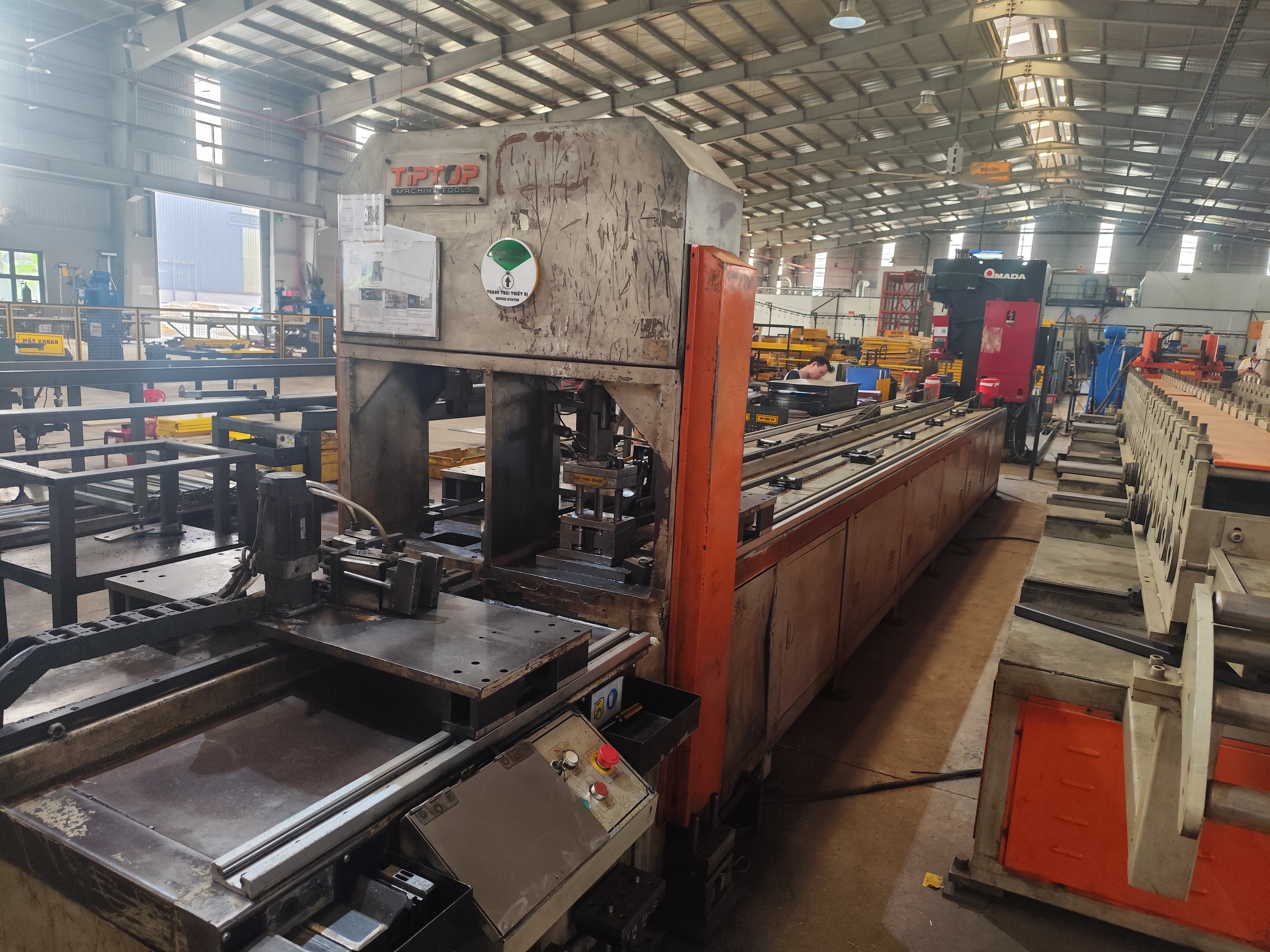
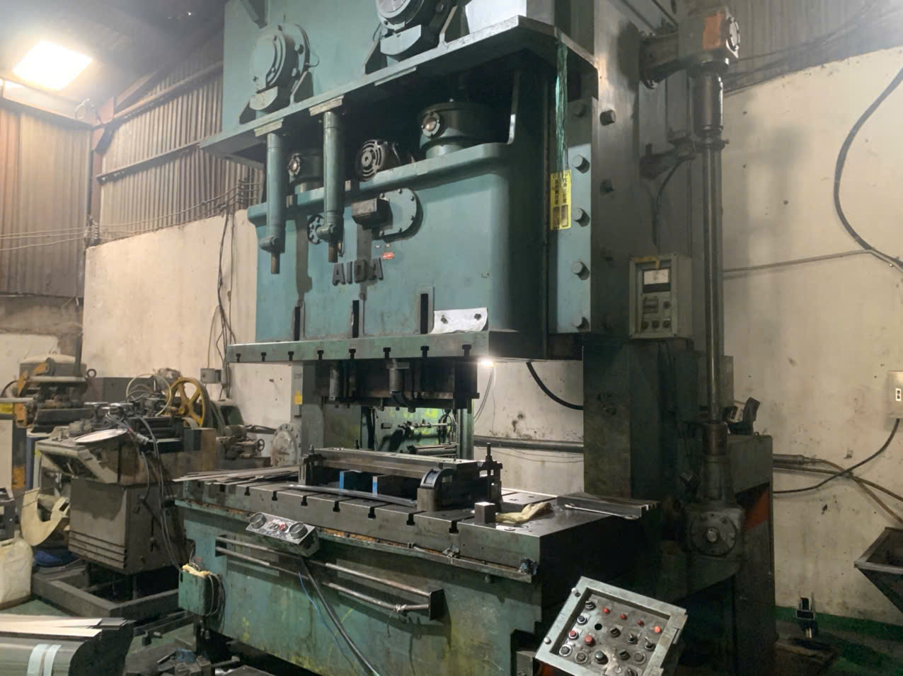
Stamping AHSS like DP800 requires roughly twice the tonnage capacity compared to HSLA 50XF. This is not a small upgrade. The press frame must be rigid enough to handle the higher forces without deflection, because frame flex translates directly into dimensional variation. Many older presses were designed for mild steel and simply cannot handle AHSS without structural modifications.
Snap-through shock is a related hazard. When cutting AHSS, the material fractures almost instantly, releasing stored energy as vibrational waves called reverse tonnage. This can damage the press, separate the upper die from the ram, and destroy tooling. Presses stamping AHSS need robust clamping systems and damping mechanisms to absorb this energy.
Servo press technology is increasingly important. Unlike mechanical presses with fixed slide motion, servo presses allow programmable stroke profiles. This means the slide speed can be reduced at the moment of material contact, managing strain rate and reducing the risk of tearing in ultra-thin sections. For parts with complex geometry, servo pulse motion profiles give the material time to flow into the die without splitting.
Tooling and Coating
High-strength steel eats tooling. The increased contact pressure raises interface temperatures, and without proper lubrication and die coatings, galling and seizure occur rapidly. Our supplier audit checklist includes verification of die material selection (D2, DC53, or powder metallurgy tool steels) and surface treatments.
| Capability | Why It Matters | How We Verify |
|---|---|---|
| High-tonnage press (≥200T for medium AHSS parts) | Prevents frame deflection and ensures consistent forming | Press specification review, on-site verification |
| Servo press or variable-speed drive | Controls strain rate, reduces tearing and springback | Equipment list review, trial run observation |
| PVD/CVD die coatings (TiAlN, CrN) | Reduces tooling wear and galling on AHSS | Tooling maintenance records, coating certificates |
| FEA simulation software | Predicts springback and stress-based failures before tooling is cut | Software license verification, sample simulation review |
| In-process SPC and monitoring | Catches dimensional drift before it becomes a batch rejection | Control plan review, SPC data sampling |
| PPAP documentation system | Ensures "right first time" through structured validation | PPAP package review (control plan, PFMEA, MSA, capability study) |
Quality System Depth
Process control is where many suppliers fall short. Having a good press is necessary but not sufficient. We look for suppliers who run Statistical Process Control 5 on critical dimensions, perform regular die maintenance on a preventive schedule, and track tool life data. For AHSS and ultra-thin work, we also verify that the supplier has real-time monitoring — whether that is load monitoring on the press or acoustic emission sensors 6 that can detect micro-cracking in thin foils before it becomes visible.
Our role as a supply chain partner is to bridge the gap between the client's engineering requirements and the supplier's shop-floor reality. We conduct supplier audits, review PPAP packages, and manage ongoing process control to make sure what was validated during first article stays consistent through production. Understanding how to evaluate a stamping parts supplier’s technical support quality is a critical part of this assessment.
How Do I Avoid Tool Wear and Cracking Problems When Stamping Ultra-Thin Materials?
A lesson we learned on a project involving 0.5 mm spring steel clips: the supplier quoted tool life at 500,000 hits. By 80,000 hits, the punch edges were chipped, burrs were out of spec, and we had to stop production for regrinding. The root cause was a combination of insufficient die material hardness and wrong lubricant for the application.
To avoid tool wear and cracking in ultra-thin stamping, use hardened tool steels with PVD or CVD coatings, apply lubricants designed for high-pressure and high-temperature forming, maintain die clearances within 0.2–0.5 times blank thickness, and implement a preventive die maintenance schedule based on actual tool life data rather than estimates.
Understanding Why Ultra-Thin Materials Destroy Tooling
It seems counterintuitive — thinner material should mean less force and less wear, right? Not with high-strength steel. The tonnage required to cut and form AHSS is driven by the material's tensile strength 7, not its thickness alone. A 0.5 mm sheet of DP980 can demand more punch force per unit length than a 1.5 mm sheet of mild steel.
The contact pressure between the punch and the die edge concentrates along a very narrow strip of material. This generates intense localized heat. Without lubricants designed for these conditions, the die surface temperature spikes, accelerating adhesive wear (galling). Galling creates rough spots on the die, which scratch subsequent parts and further increase friction in a destructive cycle.
Cracking Risks: Material and Process
Ultra-thin materials are also vulnerable to edge cracking during flanging and stretching operations. The sheared edge from a prior blanking or piercing step may contain micro-cracks. When that edge is subsequently bent or stretched, those micro-cracks propagate. A maximum thinning guideline of 20% is commonly applied to avoid performance issues, but the real-world limit depends on edge condition and material grade.
For grades exceeding 1000 MPa tensile strength, there is an additional risk of delayed cold cracking or hydrogen embrittlement 8. This is a time-dependent failure — the part looks fine after stamping but cracks hours or days later. Controlling this requires attention to material storage conditions, avoiding hydrogen pickup during cleaning or plating processes, and sometimes specifying bake-out treatments after electroplating 9. Understanding heat treatment and hardness for stamping parts is essential when specifying these post-processing steps.
Practical Countermeasures
- Die material upgrade. Move from standard D2 to powder metallurgy steels like Vanadis 4E or CPM 10V for higher wear resistance.
- Surface coatings. Apply PVD coatings such as TiAlN or AlCrN to reduce friction and resist galling. CVD coatings offer even better adhesion for long-run tooling.
- Lubrication strategy. Use boundary-film lubricants rated for the temperatures generated during AHSS forming. Water-soluble lubricants may not survive the contact pressures involved.
- Preventive maintenance. Track actual tool life in hits and schedule regrinding or replacement before burr height exceeds specification. Do not rely on the supplier's initial estimate — validate with real data.
- Edge quality management. Inspect blanked edges for micro-cracks before secondary forming. Consider laser cutting or fine blanking for critical edges where edge cracking risk is high.
Work hardening plays a role here too. AHSS work-hardens faster than conventional steels. This means the material gets harder and more abrasive as it is formed, increasing wear on subsequent stations in a progressive die. Die designers must account for this progressive increase in hardness when selecting tool materials and clearances for each station. The performance differences between stamping materials like SPCC, SUS304, and AL5052 further illustrate how material selection directly impacts tooling strategy and wear patterns.
Conclusion
High-strength steel and ultra-thin stamping demand more than standard equipment and processes. From springback compensation to tooling wear management, every step requires deliberate engineering, validated simulation, and rigorous quality control — exactly the kind of supply chain discipline we build into every project at DEWIN.
Frequently Asked Questions
How Can I Prevent Springback Issues When Stamping High-Strength Steel Parts?
One trade-off we constantly weigh with clients is geometry complexity versus springback risk. A purchasing manager once asked us to hold ±0.1 mm on a Z-shaped bracket in 980 MPa steel — cold stamped. That conversation quickly turned into a lesson on the physics of elastic recovery.
What Tolerances Should I Expect When Sourcing Ultra-Thin Stamped Components?
A buyer interaction that comes up regularly: a client sends a drawing with ±0.05 mm flatness on a 0.3 mm stainless steel clip and asks if that is realistic. The honest answer depends entirely on the geometry, the material grade, and the supplier's process control.
Which Supplier Capabilities Do I Need to Ensure Consistent Quality in High-Strength Steel Stamping?
Early in our work with high-strength steel projects, we discovered that many stamping suppliers could quote the job but few could actually run production without constant quality escapes. The gap was not in willingness — it was in equipment and process discipline.
Footnotes
1. Trade authority relevant to cross-border sourcing of stamped steel components mentioned. ↩︎
2. Official Department of Energy overview of lightweight materials, including advanced high-strength steel research. ↩︎
3. Wikipedia background on FEA simulation method used to predict springback and failures. ↩︎
4. International standards body relevant to PPAP and quality documentation systems mentioned. ↩︎
5. Background concept for SPC monitoring practices referenced for quality control. ↩︎
6. Background explanation of acoustic emission monitoring technology used for micro-crack detection. ↩︎
7. Standard technical reference for the definition and measurement of ultimate tensile strength. ↩︎
8. Comprehensive Wikipedia entry explaining the mechanism and effects of hydrogen embrittlement. ↩︎
9. Background concept for plating process linked to hydrogen pickup risk discussed. ↩︎