Every week, our team in Vietnam and China reviews dozens of sheet metal fabrication quote requests — and the single biggest cause of delays, misquotes, and rework is incomplete technical drawings.
To get an accurate sheet metal fabrication quote, you need to submit final 3D CAD models (STEP or STP format), supplemental 2D engineering drawings (PDF, DWG, or DXF) with full dimensions, material specifications, tolerance requirements, surface finish callouts, hardware details, a bill of materials for assemblies, and quantity and volume information.
This article walks through every document and detail your fabricator needs. We break it down into file formats, drawing content, quality control details, and logistics preferences. Follow this guide and you will get faster, firmer, and more accurate quotes — with fewer back-and-forth emails.
Which 2D and 3D CAD file formats do I need to submit for a precise sheet metal quote?
A lesson we learned early on: a client once sent us a set of JPEG screenshots of their CAD screen and asked for a firm quote. We spent three days going back and forth before they finally exported proper STEP files. That single format issue delayed their project by two weeks.
For a precise sheet metal quote, submit 3D CAD models in STEP (.stp), IGES (.igs), or native formats like .SLDPRT, along with supplemental 2D engineering drawings in PDF, DWG, or DXF. The 3D file is the primary input; the 2D drawing adds dimensions, notes, and inspection references.
Why 3D CAD Is Now the Primary Input
Most sheet metal fabricators today — including our partner shops across Vietnam and Taiwan — rely on 3D CAD models 1 as the starting point. The 3D file lets the fabricator unfold the part digitally, check for flat pattern feasibility, and identify potential issues with bends, cutouts, or hardware clearances before quoting. Without a 3D model, the shop must manually interpret your 2D drawing, which adds time and introduces error.
The STEP (.stp) format 2 is the universal neutral format. Nearly every CAD platform can export it, and nearly every fabricator can import it. If you use SolidWorks, you can also submit the native .SLDPRT file, which preserves feature trees and bend tables.
When 2D Drawings Are Still Required
A 2D drawing is not always mandatory for a basic quote. But it becomes essential when your part includes welding, threaded holes, or masked areas for selective surface finish. It is also required for First Article Inspection 3 using AS9102 forms 4. Think of the 2D drawing as the legal contract: it defines what the supplier must build and inspect.
For laser-cut flatwork without bends, a vector DXF file may be all you need. The DXF directly defines the cut path.
File Format Reference Table
| Format | Type | Best For | Notes |
|---|---|---|---|
| .STEP / .STP | 3D (neutral) | All sheet metal parts | Most widely accepted; submit this first |
| .SLDPRT | 3D (native SolidWorks) | SolidWorks users | Preserves bend tables and feature trees |
| .x_t (Parasolid) | 3D (neutral) | Complex geometry | Good alternative to STEP |
| .IGS / .IGES | 3D (neutral) | Surface-heavy models | Older format; still accepted |
| 2D | Dimensions, GD&T, notes | Non-editable; good for sharing | |
| .DWG | 2D (native AutoCAD) | Detailed 2D drawings | Editable by the fabricator |
| .DXF | 2D (vector) | Laser-cut flat patterns | Required for artwork or cut paths |
Export Tips
If you use SolidWorks, save your drawing as .SLDDRW for internal editing. Then export to PDF for sharing and to DXF or DWG if the fabricator needs an editable 2D file. Always export the 3D model as STEP separately. Our engineers review uploaded 2D drawings within 24 hours, but having the 3D file first cuts the review time in half.
How do I clearly specify my material, hardware, and finishing requirements in my technical drawings?
One trade-off we weigh constantly is whether to call a client for clarification on a missing material callout or just quote based on assumptions. We always call. Assumptions are where misquotes are born. A bracket quoted in mild steel versus 304 stainless can differ by 40% or more in material cost alone — which is one reason supplier quotes vary so much.
Specify material type, grade, and thickness (in both decimal inches and gauge) in the title block and general notes. Call out hardware inserts by type and thread size, model them in the 3D file when possible, and note all surface finish requirements — such as powder coating, anodizing, or chem film — directly on the drawing.

Material Specifications
Your drawing must state the exact material. "Steel" is not enough. Specify the alloy and grade: for example, "ASTM A36 mild steel" or "304 stainless steel." Include the thickness in decimal format (e.g., 0.060") and gauge (e.g., 16 GA) to avoid confusion.
If you are open to material substitutions — say, accepting 5052 aluminum instead of 6061 for cost savings — note that in the general notes. This gives the fabricator flexibility and may result in a more competitive quote. When sourcing from Vietnam or other Southeast Asian markets, we sometimes recommend equivalent regional grades, but only if the client approves the substitution in writing.
Hardware Inserts
For parts like the mounting brackets we regularly produce — with multiple pre-drilled holes and threaded inserts — hardware details are critical. hardware inserts 5 The best practice is to model each insert (PEM nuts, standoffs, studs) as a solid body in the 3D CAD file, separate from the sheet metal body but in the same assembly. If modeling is not possible, your 2D drawing must clearly call out each insert by part number, thread type (e.g., M4 × 0.7), and installation side.
| Hardware Detail | Where to Specify | Example |
|---|---|---|
| PEM nut / insert | 3D model + 2D callout | "PEM S-M4-1, install from Side A" |
| Threaded hole | 2D drawing note | "M5 × 0.8 tap, through, 3 places" |
| Weld nut | 2D weld symbol + note | "Weld nut M6, per AWS D1.1" |
| Rivet | 2D callout | "POP rivet, 3.2mm dia, 4 places" |
Surface Finish and Post-Processing
Surface finish is one of the most commonly omitted details we encounter. Your drawing should state the finish clearly: powder coating 6 (with RAL color code), anodizing (Type II or III), chem film (MIL-DTL-5541), plating, or even just "deburr all edges." If masking is needed — for example, keeping threads or mating surfaces bare — mark those areas on the 2D drawing. Weld specifications should follow standard symbols per AWS or ISO, with callouts for weld type, size, and any post-weld grinding requirements.
Bend Details and Flat Pattern
For parts with bends — like the mirrored angular brackets shown in our product line — include bend direction (up or down relative to a datum), bend angle, and inside bend radius for each bend. A flat pattern view is essential; it lets the fabricator plan nesting on the sheet and verify that the part can be formed without distortion. Keep all features at least two to three times the material thickness away from bend lines. Placing a hole too close to a bend will cause it to deform.
Edge Treatments and Detail Views
Note all edge treatments: deburring, rounding sharp corners, hems, rolled edges, or relief cuts. Use detail views for complex areas. A cluttered drawing with too many dimensions on one view is worse than a clean drawing with multiple views. At minimum, include three views: an isometric view, orthographic views (front, top, side), and a flat pattern.
What critical tolerance and quality control details must I include to ensure my parts are right the first time?
A buyer we work with in the U.S. once told us: "I don't want to inspect parts twice. I want them right the first time." That phrase stuck with our team. It became the reason we insist on complete tolerance callouts and inspection plans before production even starts.
Include all critical dimensional, angular, and geometric tolerances on your drawing, reference a general tolerance standard like ISO 2768-m for non-critical dimensions, define First Article Inspection requirements, and specify any environmental compliance needs such as RoHS or REACH to ensure your parts are right the first time.
Tolerance Requirements: What to Call Out
Not every dimension needs a tight tolerance. Over-tolerancing drives up cost because the fabricator must use slower processes and more inspection steps. Focus tight tolerances on critical features: mating surfaces, hole positions for alignment, and bend angles that affect assembly fit. For everything else, reference a general tolerance standard.
| Tolerance Type | Typical Sheet Metal Range | When to Use Tight Tolerance |
|---|---|---|
| Linear (length/width) | ±0.5 mm (general) | Mating edges, mounting surfaces |
| Hole position | ±0.25 mm | Alignment pins, fastener patterns |
| Bend angle | ±1° | Structural fits, enclosure panels |
| Hole diameter | ±0.1 mm | Press-fit hardware, precision bores |
| Flatness | 0.5 mm per 300 mm | Sealing surfaces, optical mounts |
ISO 2768-m 7 (medium) is a common general tolerance standard for sheet metal. Stating it in your title block saves space on the drawing and sets a baseline expectation. If your project requires tighter control, call out specific GD&T symbols (position, flatness, perpendicularity) on the features that matter.
First Article Inspection and Quality Documentation
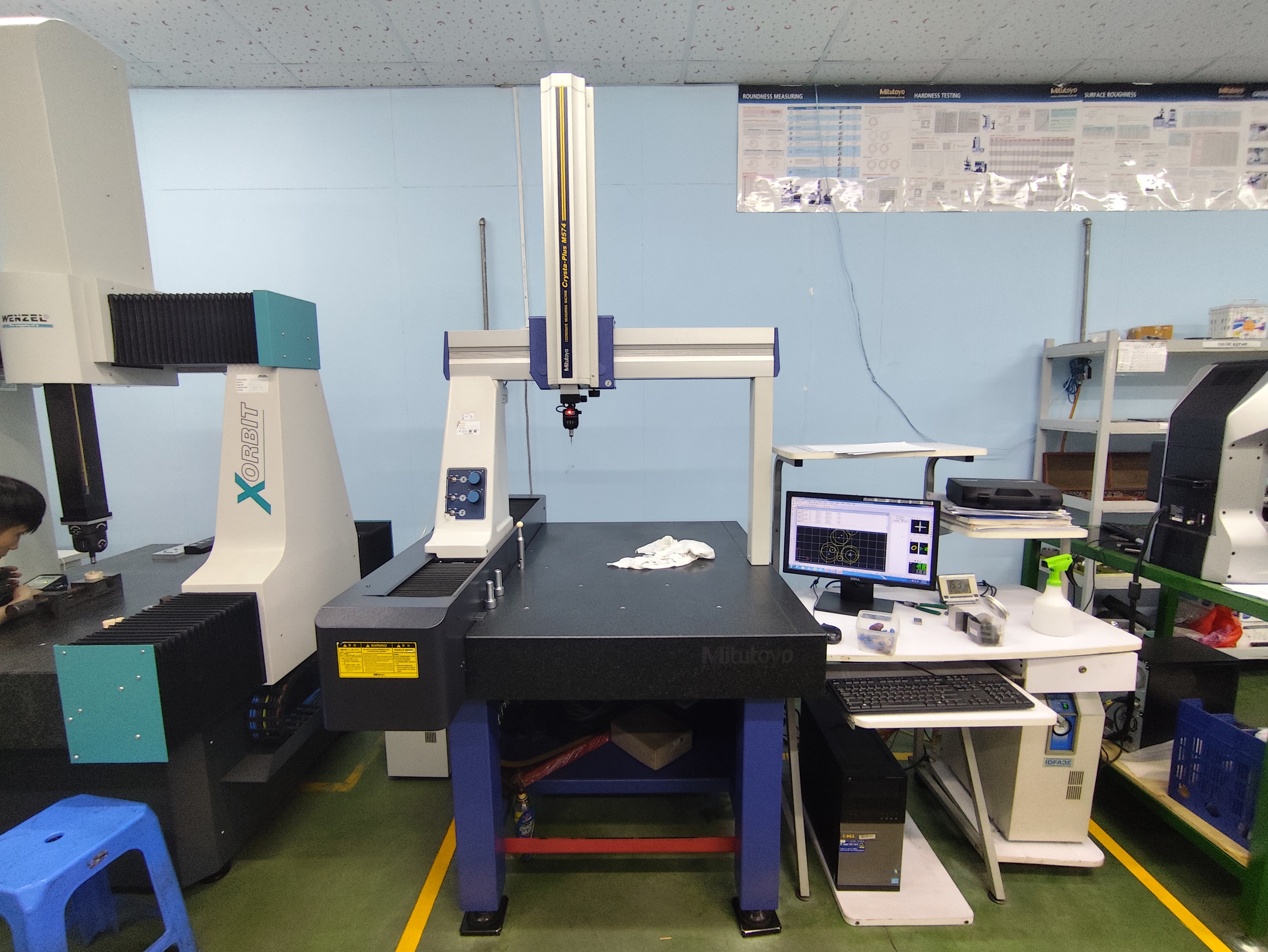
If your project requires a First Article Inspection, state it clearly in your RFQ package. FAI per AS9102 is common in aerospace, but many commercial buyers also request it for critical assemblies. Our process control team prepares full FAI reports — including dimensional measurements, material certifications, and process records — as part of our PPAP deliverables.
Specify which inspection method you expect: CMM measurement, optical comparator, go/no-go gauges, or visual inspection. If you need mill certifications or material traceability certificates, note that in your general notes. This affects material sourcing and lead time, especially when sourcing from Southeast Asian suppliers where certain certified grades may have longer procurement cycles.
Design for Manufacturability Feedback
A good fabricator will review your drawings for Design for Manufacturability before quoting. This DFM review catches issues that would cause problems in production: features too close to bends, impractical bend sequences, or material choices that don't form well. At DEWIN, we include a DFM review as a standard part of our quoting process. We flag potential issues and suggest alternatives before you commit to tooling or production.
Environmental Compliance
If your end product must meet RoHS, REACH, or other environmental regulations, document that requirement on the drawing or in the RFQ cover letter. Compliance affects material sourcing — for example, certain plating chemistries are restricted under RoHS. It may also require additional documentation such as compliance certificates or restricted substance declarations.
Expected Service Environment
Providing context on where and how the part will be used helps your fabricator make better recommendations. A bracket destined for outdoor marine use needs different material and finish choices than one going inside a climate-controlled server rack. Include a note about the service environment when it affects material selection or surface finish durability.
Do I need to provide my logistics and credit term preferences along with my engineering documents?
When we first started working with U.S. sourcing companies, we noticed that engineering teams and procurement teams often operate on different timelines. The engineer sends perfect drawings. The purchasing manager sends a separate email weeks later asking about freight terms and payment conditions. This disconnect slows everything down.
Yes — include your logistics preferences (shipping method, delivery destination, Incoterms) and credit term requirements (such as Net 60 or Net 90) alongside your engineering documents. This information allows the fabricator to provide a complete, landed-cost quote and avoids delays in commercial negotiations.
Building a Complete RFQ Package
An RFQ package is more than just a drawing. It is a consolidated set of documents that gives the fabricator everything needed to quote accurately. Here is what a complete package should include:
- 3D CAD models (STEP format preferred)
- 2D engineering drawings 8 (PDF + DWG/DXF)
- Bill of materials for assemblies
- Material list with type, size, and quantity of each part
- Assembly instructions or step-by-step build sequences for complex weldments
- Quantity and volume information (prototype vs. production, annual forecast)
- Target lead time
- Logistics preferences (FOB, CIF, DDP, delivery address)
- Payment term preferences (Net 30, Net 60, Net 90, or open account)
Why Logistics and Payment Terms Matter for Quoting
Shipping method affects total cost. Air freight for a rush order of heavy steel brackets costs dramatically more than ocean freight with a standard lead time. If you specify your preferred Incoterms 9 (e.g., DDP to a U.S. warehouse), the fabricator can include freight, duties, and insurance in the quote. Otherwise, you get a factory-gate price that does not reflect your true landed cost.
Payment terms also influence pricing. At DEWIN, we offer open account terms (Net 60 to Net 90) to qualified U.S. clients. This alleviates cash flow pressure on the buyer's side, but it does factor into the overall commercial arrangement. Mentioning your preferred terms upfront lets the fabricator build a quote that reflects the full scope of the business relationship.
Quantity, Volume, and Recurring Needs
State exact quantities. A quote for 10 prototype brackets is very different from a quote for 5,000 production units. Tooling amortization, material purchasing leverage, and setup time all shift with volume — understanding how prototyping and mass production differ is key to setting the right expectations. If you anticipate recurring orders — say, 1,000 pieces per quarter — mention that. It may unlock better unit pricing and dedicated tooling.
| RFQ Detail | Why It Matters | Impact on Quote |
|---|---|---|
| Quantity | Determines setup amortization | Higher volume = lower unit cost |
| Annual forecast | Enables blanket pricing | Better material purchasing leverage |
| Lead time | Affects scheduling and freight | Rush orders cost more |
| Incoterms | Defines cost responsibility | DDP includes freight + duties |
| Payment terms | Affects cash flow and risk | Open account may adjust pricing |
| Delivery address | Determines freight cost | Inland vs. port city matters |
Grouping Parts for Efficient Quoting
If your RFQ includes many similar parts — for example, a family of brackets in the same material and finish — group them together. This lets the fabricator batch-quote using shared setup and nesting. For complex assemblies, include clear assembly instructions and a bill of materials that ties each component to its drawing number. Our project management team in Singapore coordinates these multi-part quotes across our Vietnam and China offices to ensure nothing falls through the cracks.
Conclusion
Getting an accurate sheet metal fabrication quote starts with submitting complete, fabrication-ready documents: 3D CAD models, 2D engineering drawings, material specifications 10, tolerance requirements, and a full RFQ package including logistics and payment terms. Invest the time upfront, and you avoid costly delays and rework downstream. For a deeper dive into all the technical documents and parameters required for a sheet metal fabrication quote, explore our detailed checklist. Contact us at sa***@*******ch.com to get started.
Frequently Asked Questions
Which 2D and 3D CAD file formats do I need to submit for a precise sheet metal quote?
A lesson we learned early on: a client once sent us a set of JPEG screenshots of their CAD screen and asked for a firm quote. We spent three days going back and forth before they finally exported proper STEP files. That single format issue delayed their project by two weeks.
How do I clearly specify my material, hardware, and finishing requirements in my technical drawings?
One trade-off we weigh constantly is whether to call a client for clarification on a missing material callout or just quote based on assumptions. We always call. Assumptions are where misquotes are born. A bracket quoted in mild steel versus 304 stainless can differ by 40% or more in material cost alone — which is one reason supplier quotes vary so much .
What critical tolerance and quality control details must I include to ensure my parts are right the first time?
A buyer we work with in the U.S. once told us: "I don't want to inspect parts twice. I want them right the first time." That phrase stuck with our team. It became the reason we insist on complete tolerance callouts and inspection plans before production even starts.
Footnotes
1. Provides a comprehensive overview of computer-aided design and its applications. ↩︎
2. Explains the STEP file format, its purpose, and interoperability in CAD. ↩︎
3. Defines First Article Inspection and its importance in quality assurance. ↩︎
4. Guide to AS9102 First Article Inspection standard for aerospace and defense. ↩︎
5. Introduces various types of hardware inserts and their applications in manufacturing. ↩︎
6. Provides a general overview of powder coating, its process, and applications. ↩︎
7. Explains the ISO 2768 standard for general tolerances in sheet metal. ↩︎
8. Details the importance and components of technical drawings in manufacturing. ↩︎
9. Explains Incoterms and their role in international trade and shipping responsibilities. ↩︎
10. Highlights the critical role of material specifications in manufacturing quality and safety. ↩︎