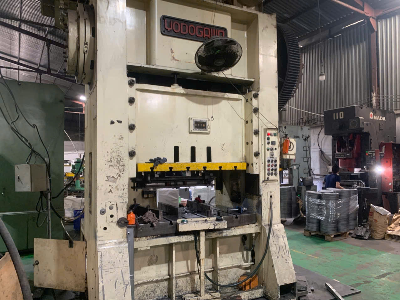
What applications rely on custom stamped aerospace components?
Custom stamped aerospace components and aerospace pressed parts are used in airframe brackets and ribs, flight control hardware, avionics enclosures, EMI shielding, fuel and oxygen system parts, engine sensors, landing gear reinforcement plates, antenna mounts, and custom stamped aerospace fasteners like clips, shims, and retainers across high-volume production schedules.
Key Takeaways
- Aerospace pressed parts are used across airframe brackets, flight control hardware, avionics shielding, fuel systems, and custom stamped aerospace fasteners.
- Common materials for aeronautical stamping part design include aluminum alloys (2024, 6061, 7075), stainless steels, titanium, and copper alloys.
- Critical punched features can hold tolerances of ±0.05 mm to ±0.13 mm, while formed bends range from ±0.1 mm to ±0.25 mm.
- Supplier reliability relies on AS9100-aligned quality systems, mill cert traceability, PPAP/FAI validation, and on-site die maintenance audits.
Stamped components provide vital support throughout an aircraft structure. While rarely highlighted, a single out-of-spec bracket can halt complete assembly schedules and create costly rework. Ensuring stampings meet precise drawing notes prevents groundings and keeps production moving.
- Airframe brackets, ribs, and panels
- Flight control hardware
- Avionics enclosures and EMI shielding
- Fuel and oxygen system components
- Engine sensors and valves
- Landing gear reinforcement plates and antenna mounts
- High-volume fasteners including clips, shims, and retainers

Which materials fit aeronautical stamping part design requirements?
Aeronautical stamping part design balances weight, strength, and operating environment. Aluminum alloys like 2024, 6061, and 7075 provide lightweight structural strength for airframes. Stainless steel (301, 304, 17-7 PH) handles spring fasteners and corrosive zones, titanium suits high-heat engine areas, and copper alloys offer electrical conductivity for avionics shielding.
Every material selection involves trade-offs between weight budget, mechanical load, and operating environment. Aluminum remains the leading choice for structural components due to weight savings across thousands of airframe parts. For higher vibration or elevated temperature zones near engines, stainless steel or titanium alloys are selected.
Formability must also be evaluated during design. High-strength alloys can crack during tight bending if the temper and bend radius are not planned together. Hot stamping of high-performance aluminum is expanding options for larger curved structural parts that once required full machining.
- Aluminum alloys (2024, 6061, 7075): Lightweight, formable; used in airframe brackets, ribs, panels, and housings.
- Stainless steel (301, 304, 17-7 PH): Corrosion resistant with spring properties; used in clips, retainers, and fuel system parts.
- Titanium alloys (CP Ti, Ti-6Al-4V): High strength-to-weight ratio and heat tolerance; used in engine-area brackets and heat shields.
- Copper alloys (Beryllium copper, phosphor bronze): Conductive; used in connectors, terminals, and EMI shielding.
What tolerances apply to custom stamped aerospace fasteners and parts?
Aerospace pressed parts typically hold ±0.05 mm to ±0.13 mm on critical punched features, ±0.1 mm to ±0.25 mm on formed bends, and ±0.5° to ±1° on bend angles. Precision micro-stamped contacts can achieve ±0.02 mm. Punched holes remain stable, whereas formed dimensions experience springback based on material alloy and temper.
Tolerance expectations must align with specific part features rather than blanket drawing notes. Punched features hold tight boundaries because the tool steel controls them directly, whereas formed dimensions accumulate variation from sheet thickness and material springback.
Overly tight non-critical callouts significantly increase tooling and inspection expenses. Specifying critical dimensions clearly prevents suppliers from quoting defensively, while using progressive dies helps stabilize positional relationships across multiple forming steps.
- Punched hole diameter: ±0.05 mm
- Hole-to-hole position: ±0.05 to ±0.1 mm
- Blank profile and edges: ±0.1 mm
- Formed height and bend location: ±0.1 to ±0.25 mm
- Bend angle: ±0.5° to ±1°
- Flatness: 0.1 to 0.3 mm typical
- Micro-stamped contacts: Down to ±0.02 mm

How can buyers qualify suppliers for custom stamped aerospace parts?
Qualifying suppliers for custom stamped aerospace components requires evaluating quality certifications, conducting on-site press line audits of die maintenance and gauge calibration, validating initial samples through PPAP or first-article inspection reports, checking heat-lot material traceability back to mill certs, and monitoring ongoing production using statistical process control charts.
Finding press shops is simple, but verifying operational discipline requires structured evaluation. A physical audit confirms raw material control, die maintenance practices, and metrology calibration before placing initial orders.
Initial sample validation through first-article reports ensures the press setup consistently achieves drawing specifications across all features before full production approval.
- Screen on paper: Review quality system certifications, equipment lists, tonnage range, and customer history.
- Audit on-site: Inspect press lines, die maintenance records, gauge calibration, and raw material storage.
- Test with first articles: Evaluate technical responsiveness on real drawings with specified tolerances.
- Validate with PPAP: Require full dimensional reports, material certs, and process flow documentation.
- Control production ramp: Maintain in-process checks and pre-shipment inspections on early production lots.
Engineering & Production Specification Matrix
| Process Parameter | Prototype / Short-Run Standard | Production Progressive / Hard-Tool Standard | Verification Method |
|---|---|---|---|
| Linear Dimensional Tolerance | ±0.10 mm to ±0.15 mm (ISO 2768-m) | ±0.03 mm to ±0.08 mm (ISO 2768-f) | Optical 2D/3D CMM & Go/No-Go Check Fixtures |
| Edge Burr Height Limit | ≤ 10% of material thickness | ≤ 5%–8% of material thickness | Digital Micrometer & Cross-Section Audit |
| Material & Coating Traceability | Mill Test Certificate (EN 10204 3.1) | Heat-lot MTC + RoHS/REACH + ASTM B117 Salt-Spray | Spectrometer (OES) & XRF Screening |
| Standard Tooling & Lead Time | Laser + CNC Press Brake (5–10 days) | Progressive / Transfer Die (3–5 weeks T1) | First Article Inspection (FAI) & CPK ≥ 1.33 |
Frequently Asked Questions
What causes variation in formed stamped aerospace dimensions?
Formed dimensions experience higher variation than punched features due to material springback, raw stock thickness variations, and die wear across bend radii. Overbending in the tooling and using restrike steps help stabilize final bend angles and locations.
Why are mill certificates required for stamped aerospace parts?
Mill certificates establish full material traceability from raw heat lots to finished components. This documentation verifies that sheet stock meets drawing specifications and enables rapid lot containment if a defect occurs.
How does tool review during design prevent stamping defects?
Reviewing bend radii against alloy temper before cutting dies prevents cracking in high-strength metals such as 7075 aluminum. Evaluating geometry early eliminates expensive die modifications and avoids secondary machining.
What role does progressive die tooling play in aerospace stamping?
Progressive dies execute multiple blanking and forming steps in one continuous pass. This maintains accurate positional tolerances between hole patterns and formed features while reducing labor costs.