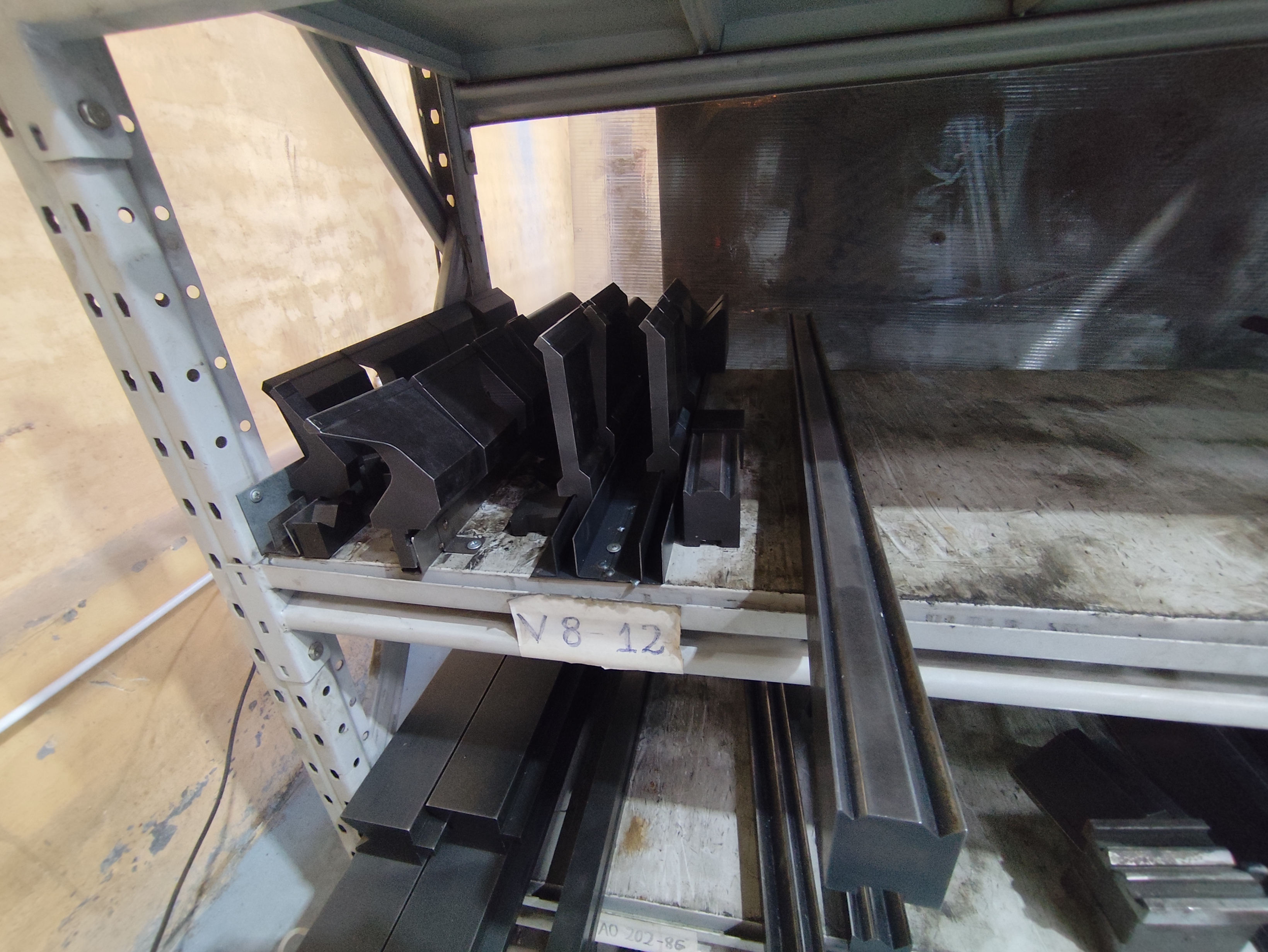
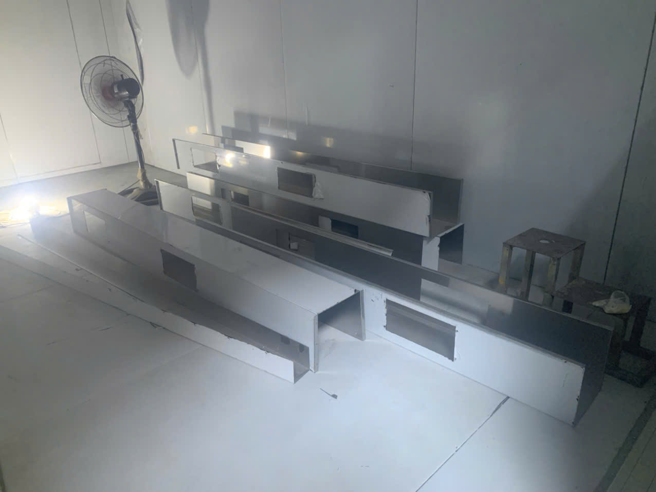
Last month, a U.S. client sent us a bracket drawing with tight angle callouts — and their previous supplier kept missing them standard press brake operations 1. That frustration is common, and it points to a deeper question about what bending angle accuracy you can realistically expect.
The typical bending angle accuracy range in sheet metal fabrication is ±1° for standard press brake operations and ±0.5° for high-precision CNC bending. Linear dimensional tolerances generally fall between ±0.1 mm and ±0.5 mm, depending on material type, tooling condition, and the number of bends involved.
Understanding these ranges helps you set realistic expectations, avoid unnecessary rejections, and communicate clearly with your fabrication partner Linear dimensional tolerances 2. Below, we break down how tolerances are determined, what drives variation, how to verify quality, and whether precision sourcing from Vietnam is viable.
How do I determine the standard bending tolerances for my custom sheet metal parts?
A purchasing manager we work with in the Midwest once told us he spent three months arguing with a supplier over tolerance callouts that were never realistic for the process Tolerance Stack-Up 3. That experience taught both sides an important lesson about starting with the right baseline.
To determine standard bending tolerances, reference industry norms: ±1° for angle and ±0.20 mm for linear dimensions in standard processes, or ±0.5° and ±0.05 mm for high-precision CNC bending. Then adjust based on your material, number of bends, and functional requirements.
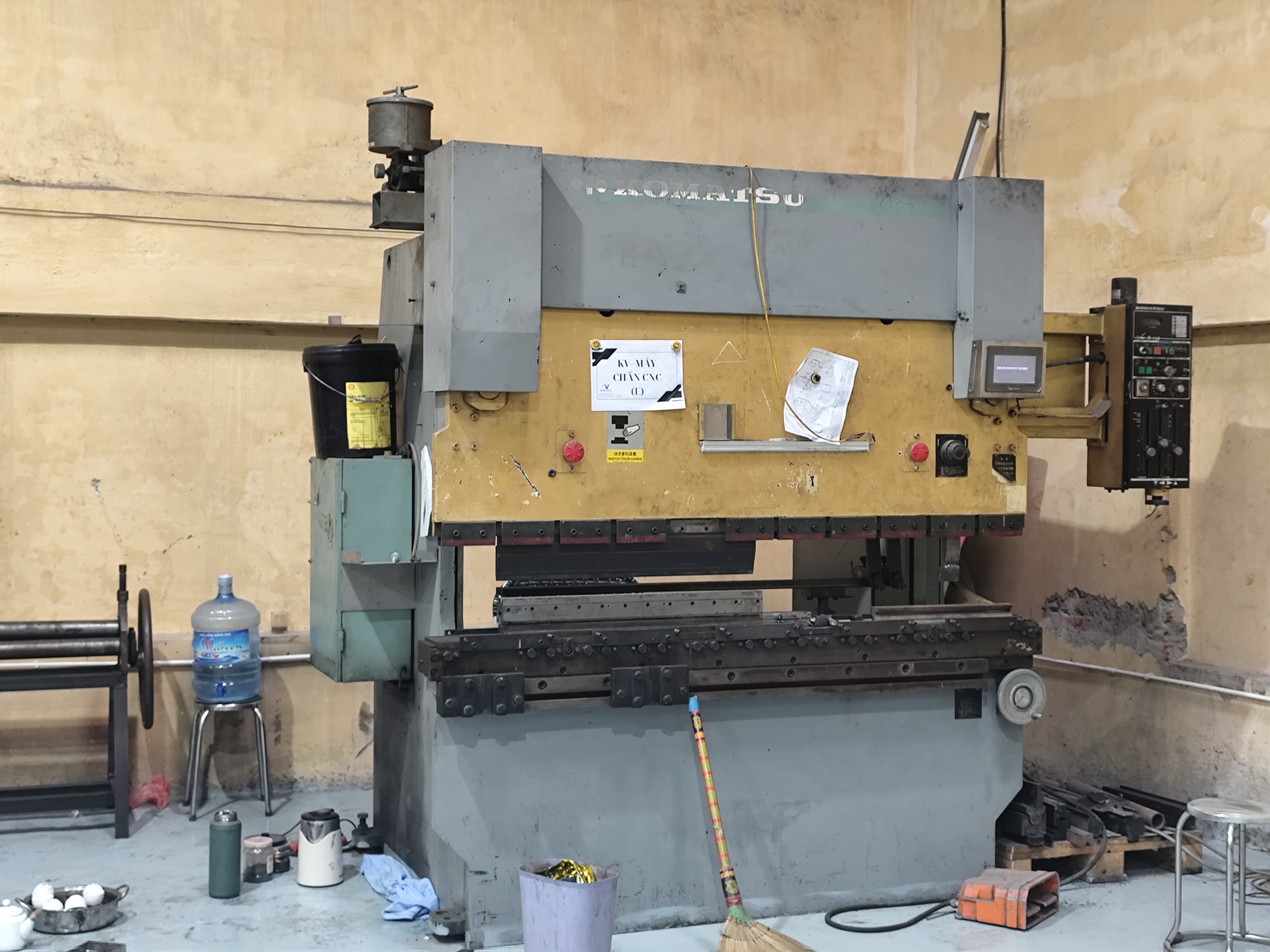
Standard vs. High-Precision Tolerance Ranges
The first step is knowing what the process can deliver before you specify what you need First Article Inspection Report (FAIR) 4. Here is a quick reference:
| Parameter | Standard Bending | CNC Bending | High-Precision Bending |
|---|---|---|---|
| Angle tolerance | ±1° | ±1° (±0.5° with feedback) | ±0.5° or better |
| Linear tolerance per bend | ±0.20 mm | ±0.18 mm | ±0.05 mm |
| Bending height precision | ±0.25 mm | ±0.20 mm | ±0.10 mm |
| Post-bending length | ±0.5 mm | ±0.35 mm | ±0.15 mm |
Most custom parts we process for U.S. buyers fall into the CNC bending category. Standard bending is fine for structural brackets and non-critical enclosures Statistical Process Control (SPC) 5. High-precision bending is reserved for parts with tight mating surfaces or assembly interfaces.
How to Set Realistic Tolerances
Start with a simple rule of thumb. Take the laser-cut base tolerance of approximately ±0.05 mm. Then add about ±0.13 mm for every bend. A part with two bends might realistically hold ±0.31 mm on key dimensions. If your design has four bends, expect cumulative error to push toward ±0.57 mm or more.
Non-critical features should carry a tolerance of ±0.76 mm (about ±0.030"). For moderately important dimensions, ±0.38 mm (±0.015") is achievable. Only specify ±0.25 mm (±0.010") or tighter when the function truly demands it — because tighter tolerances mean more inspection, slower production, and higher cost.
Account for Tolerance Stack-Up
Each bend introduces its own positional and angular error. When multiple bends exist on the same part, those errors stack. We always review multi-bend parts during our DFM check. If we see five or six bends on a single bracket, we flag it early. We might suggest redesigning one feature as a weld or a separate piece to keep cumulative error in check.
In our experience supporting engineering design firms, the most common mistake is over-specifying every dimension. Identify the two or three critical features — usually mating holes or interface surfaces — and hold those tight. Let everything else float within standard precision and tolerance ranges. This approach speeds production and reduces scrap without sacrificing fit.
What factors are causing variations in my sheet metal bending angle accuracy?
One lesson we learned early on in our Vietnam facility was that two batches of the same grade stainless steel from two different mills bent differently. Same thickness on the cert. Same die setup. Different results. That inconsistency is not a mystery — it has specific, identifiable causes.
Variations in bending angle accuracy stem from material property differences, springback behavior, tooling wear, machine calibration drift, operator skill level, and bend sequencing. Material thickness variation alone can shift the final angle by 1–2°, making process control across all these factors essential.
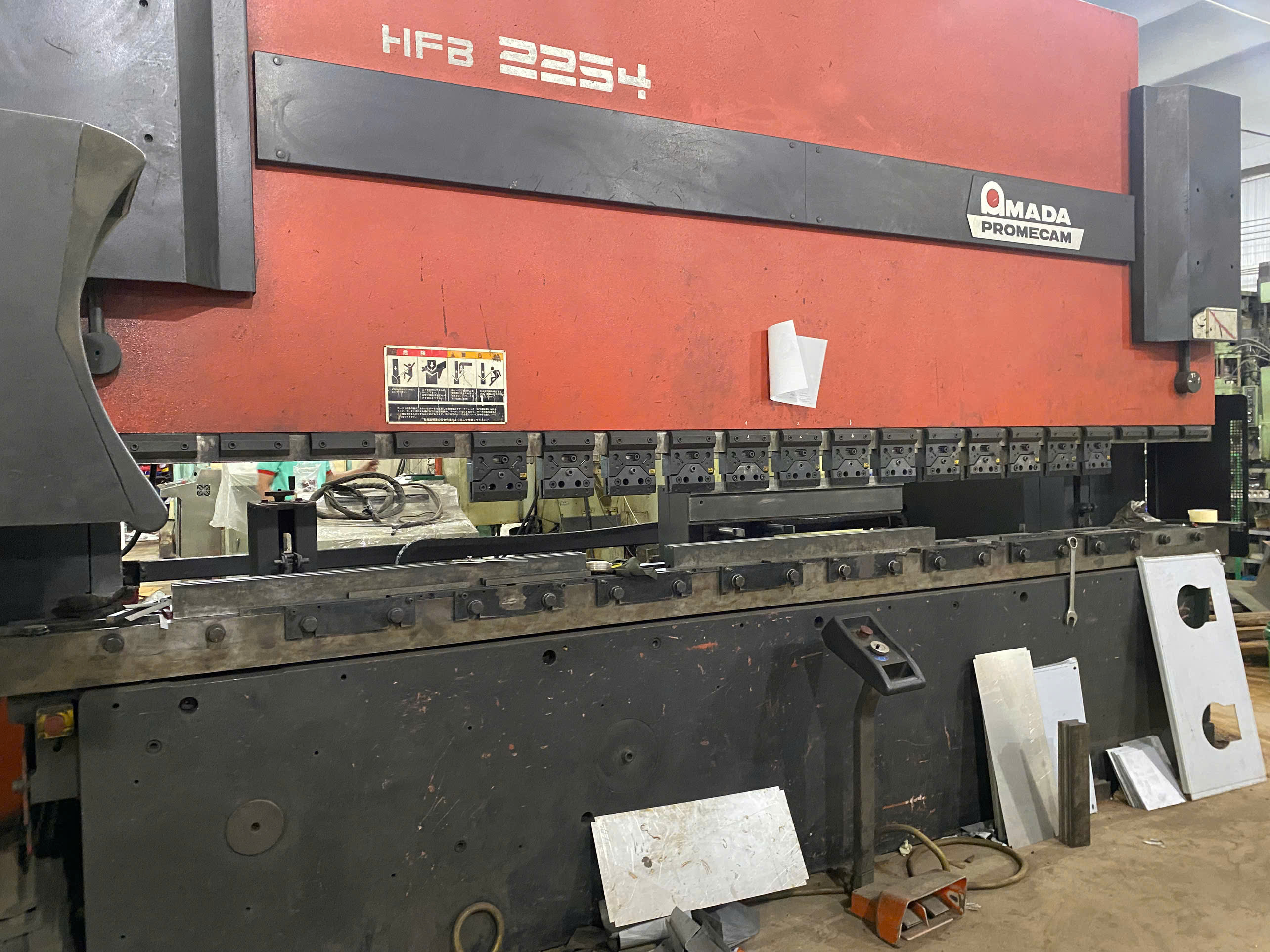
Material Properties and Springback
Springback is the single biggest source of angle variation. When the punch retracts, the metal partially springs back toward its original shape. This effect typically adds 1–2° of error. Harder materials like stainless steel and high-strength aluminum spring back more than mild steel.
The K-factor 7 — which defines where the neutral axis sits during bending — varies with material type, thickness, and bend radius. A K-factor miscalculation directly changes the bend allowance, which shifts both the angle and the final flange length. Most CAD systems default to a K-factor of approximately 0.5, but real-world values differ. Our engineering team verifies K-factors during first-article production rather than trusting defaults.
Material thickness variation is another culprit. Mill tolerances allow thickness to vary by ±0.05 mm or more. On thin-gauge parts (under 1.5 mm), that variation is proportionally large enough to change the bend result.
Tooling and Machine Factors
| Factor | Impact on Angle | Typical Magnitude |
|---|---|---|
| Tooling wear (punch radius erosion) | Inconsistent bend radius → angle drift | 0.5–1.5° over tool life |
| Die opening width mismatch | Over/under bending | 1–2° |
| Machine calibration drift | Ram depth inaccuracy | 0.5–1° |
| Back gauge positioning error | Flange length error → apparent angle error | 0.1–0.3 mm per bend |
| Operator skill (manual adjustment) | Setup and in-process correction quality | Varies widely |
Press brake accuracy depends on regular machine calibration. Ram parallelism, depth repeatability, and crowning compensation all affect the result. A well-maintained CNC press brake with real-time angle measurement can detect and correct drift mid-cycle. Without those sensors, the operator must check samples manually.
Bending Method Matters
Air bending 8 is the most common method. It is flexible because you can achieve different angles with the same die. But it is also the most sensitive to material variation and springback. Bottoming and coining apply more force and produce more consistent angles. Coining can virtually eliminate springback, but it requires much higher tonnage and dedicated tooling.
For most custom parts we produce, air bending with springback compensation in the CNC program delivers the best balance of flexibility and press brake accuracy. When a project calls for ±0.5° or tighter, we move to bottoming or add in-process angle measurement.
Bend Sequencing and Part Geometry
Improper bend sequencing causes interference between the part and the tooling. It can also introduce distortion if earlier bends create internal stresses that affect later bends. Our process engineers plan the bend sequence during DFM review. Complex brackets with five or more bends always get a simulation check before the first piece runs.
How can I ensure my supplier's QC process maintains my required bending precision?
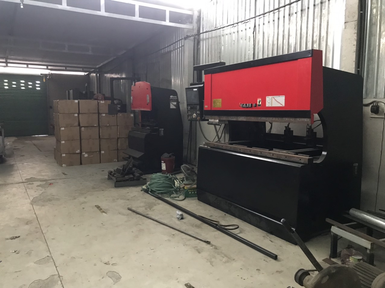
During a recent supplier audit at a factory in Ho Chi Minh City, we found that the shop had a modern CNC press brake — but no documented inspection procedure for bent parts. The machine was capable, yet nobody was verifying the output against the drawing. Capability without verification means nothing.
To ensure your supplier maintains bending precision, require a documented QC process that includes first-article inspection with measured angle and dimensional data, in-process checks at defined intervals, calibrated measurement tools, and a clear corrective action procedure when parts drift out of tolerance.
What to Look for in a Supplier's QC System
A capable supplier should demonstrate these elements:
- First Article Inspection Report (FAIR): Before running production, the first piece is fully measured. Angle and dimensional accuracy data are recorded against every callout on the drawing.
- In-Process Inspection Frequency: Not just first and last piece. A defined sampling plan — such as every 20th or 50th part — catches drift before it becomes a batch problem.
- Calibrated Instruments: Protractors, digital angle gauges, vernier calipers, CMMs. Ask for calibration certificates. Vernier caliper measurements on bent parts typically show 0.2–0.7 mm variance against nominal, so the tool must be appropriate for the tolerance being verified.
- Statistical Process Control (SPC): For high-volume or critical-tolerance parts, SPC charts track trends. A process drifting toward the tolerance limit gets corrected before it produces scrap.
- Corrective Action Process: When out-of-spec parts are found, what happens? A good supplier isolates, investigates root cause, and implements a fix — not just reworks and ships.
Measurement Challenges on Bent Parts
Measuring bent parts is harder than measuring flat ones. Surface deformations of 0.1–0.2 mm near the bend line are normal. These irregularities can fool a caliper or a flat gauge. Feeler gauge clearance readings typically range from 0.05 to 0.25 mm, with maximum deviation of about 0.15 mm from nominal.
For critical angles, optical or laser angle measurement tools give better results than contact methods. We have seen suppliers report "pass" on angles that were actually 1.5° off because they used the wrong measurement method.
Our Approach to Supplier Quality Management
Our team in Vietnam conducts process audits — not just product inspections. We verify that the press brake is calibrated, that the operator follows the setup sheet, and that in-process checks actually happen at the documented frequency. We also review the PPAP package before any production shipment, which includes dimensional data, material certs, and process capability studies.
For projects where dimensional accuracy is critical, we specify PPAP Level 3 9 with full measurement reports. This gives our U.S. clients traceability from raw material through final bend.
| QC Element | What to Verify | Red Flag |
|---|---|---|
| FAIR | All critical dims measured, angles reported in degrees | Missing angle data or "visual OK" only |
| In-process sampling | Defined frequency, documented results | "We check sometimes" with no records |
| Measurement tools | Calibrated, appropriate resolution | Expired calibration stickers, wrong tool for tolerance |
| Corrective action | Written procedure, root cause analysis | No documentation of past issues |
| Machine calibration | Annual or semi-annual records | No records or lapsed schedule |
This table is what we use internally when auditing a new bending supplier. If any red flag appears, we address it before placing an order — not after the first shipment arrives short.
Can I achieve high-precision bending results when sourcing from manufacturers in Vietnam?
A client asked us this question directly two years ago. He had been sourcing complex mounting brackets from a supplier in eastern China and was exploring alternatives due to tariff pressures. His concern was legitimate: could a Vietnamese factory match the precision he was used to?
Yes, high-precision bending results are achievable from Vietnam-based manufacturers. Factories equipped with modern CNC press brakes, real-time angle measurement systems, and trained operators routinely hold ±0.5° angle tolerances and ±0.1 mm dimensional accuracy on custom sheet metal components.
The State of Sheet Metal Fabrication in Vietnam
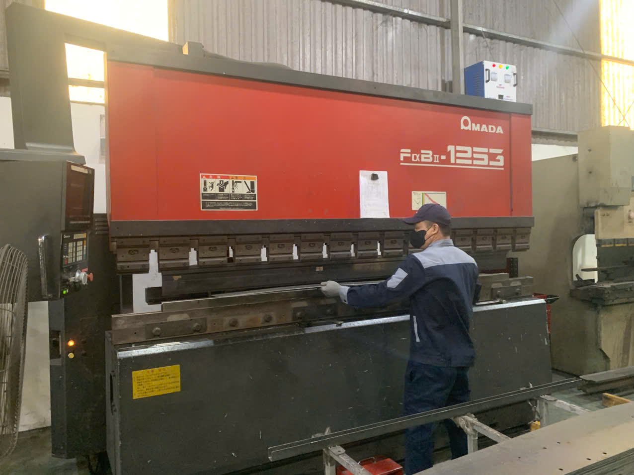
Vietnam's manufacturing sector has matured significantly. Major industrial zones near Ho Chi Minh City and Hanoi now host factories with Amada, Trumpf, and Bystronic press brakes — the same equipment found in top-tier shops worldwide. The gap is not in machinery. It is in process discipline, engineering support, and quality culture.
That is exactly where our role adds value. Our seven-person team based in Vietnam provides on-site process oversight. We do not just inspect finished parts. We participate in DFM reviews, validate bend sequences, witness first-article runs, and audit in-process controls. This hands-on involvement bridges the gap between machine capability and consistent output.
Where Vietnam Excels — and Where to Watch Out
Vietnam is strong on cost competitiveness and increasingly capable on mid-to-high precision work. Labor costs remain lower than China's coastal regions, and trade policy alignment with the U.S. offers tariff advantages. However, some challenges exist:
- Operator skill variation: Training programs are improving, but not all shops have experienced press brake operators. We vet operator competency as part of our supplier qualification.
- Material sourcing: Vietnamese mills produce a narrower range of sheet metal grades than Chinese or Korean mills. For exotic alloys or tight-tolerance material, the steel may still be imported, adding lead time.
- Engineering communication: Drawing interpretation issues are real. Metric vs. imperial confusion, GD&T misunderstanding, and missed notes cause first-article failures. Our bilingual engineering team reviews every drawing before release to the factory floor.
Real-World Precision Achievable in Vietnam
| Capability | Vietnam (Qualified Supplier) | Typical Industry Standard |
|---|---|---|
| CNC press brake angle accuracy | ±0.5° with real-time measurement | ±1° standard, ±0.5° high precision |
| Linear tolerance per bend | ±0.10–0.15 mm | ±0.13–0.20 mm |
| Springback compensation | Programmed in CNC, verified at FAIR | Varies by operator and shop |
| Multi-bend cumulative tolerance | ±0.4–0.6 mm (3–4 bends) | ±0.5–0.75 mm |
| Surface finish near bends | Controlled, minimal marking | 0.1–0.2 mm deformation typical |
These numbers come from actual production data on brackets and enclosure parts we have managed through Vietnamese suppliers. With the right supplier and the right oversight, Vietnam delivers precision comparable to established alternatives.
Technology Adoption Is Accelerating
We are seeing Vietnamese shops adopt bend simulation software integrated into their CAD/CAM workflows. This lets them predict springback and optimize bend sequences before cutting a single blank. Some shops have also invested in AI-assisted parameter optimization, where historical bending data trains algorithms to predict optimal tonnage and depth for new materials.
Additive manufacturing of custom tooling is another emerging trend. Instead of waiting weeks for a specialty punch profile, some factories 3D-print prototype dies for short-run or complex-geometry bends. This speeds up first-article turnaround considerably.
The combination of modern equipment, digital tools, and local quality management makes Vietnam a credible source for precision sheet metal fabrication — not just for commodity work.
Conclusion
Bending angle accuracy depends on your process, material, tooling, and quality controls — not guesswork. Set realistic tolerances, verify your supplier's QC rigor, and consider Vietnam as a precision-capable sourcing option with the right oversight partner.
Frequently Asked Questions
How do I determine the standard bending tolerances for my custom sheet metal parts?
A purchasing manager we work with in the Midwest once told us he spent three months arguing with a supplier over tolerance callouts that were never realistic for the process Tolerance Stack-Up 3 . That experience taught both sides an important lesson about starting with the right baseline.
What factors are causing variations in my sheet metal bending angle accuracy?
One lesson we learned early on in our Vietnam facility was that two batches of the same grade stainless steel from two different mills bent differently. Same thickness on the cert. Same die setup. Different results. That inconsistency is not a mystery — it has specific, identifiable causes.
How can I ensure my supplier's QC process maintains my required bending precision?
During a recent supplier audit at a factory in Ho Chi Minh City, we found that the shop had a modern CNC press brake — but no documented inspection procedure for bent parts. The machine was capable, yet nobody was verifying the output against the drawing. Capability without verification means nothing.
Footnotes
1. Discusses ideal press brake tolerances and benchmarks for precision. ↩︎
2. Provides a clear definition and application of linear dimensional tolerances in fabrication. ↩︎
3. Wikipedia provides an authoritative explanation of tolerance analysis, including tolerance stack-ups. ↩︎
4. Offers a comprehensive explanation of FAIR and its importance in manufacturing. ↩︎
5. Defines SPC as a methodology for monitoring and improving manufacturing processes. ↩︎
6. Provides a clear definition and explanation of springback in sheet metal bending. ↩︎
7. Clearly defines K-factor and its importance in sheet metal bending calculations. ↩︎
8. Provides a comprehensive explanation of the air bending process and its advantages. ↩︎
9. Outlines the requirements and documentation for PPAP Level 3 submission. ↩︎