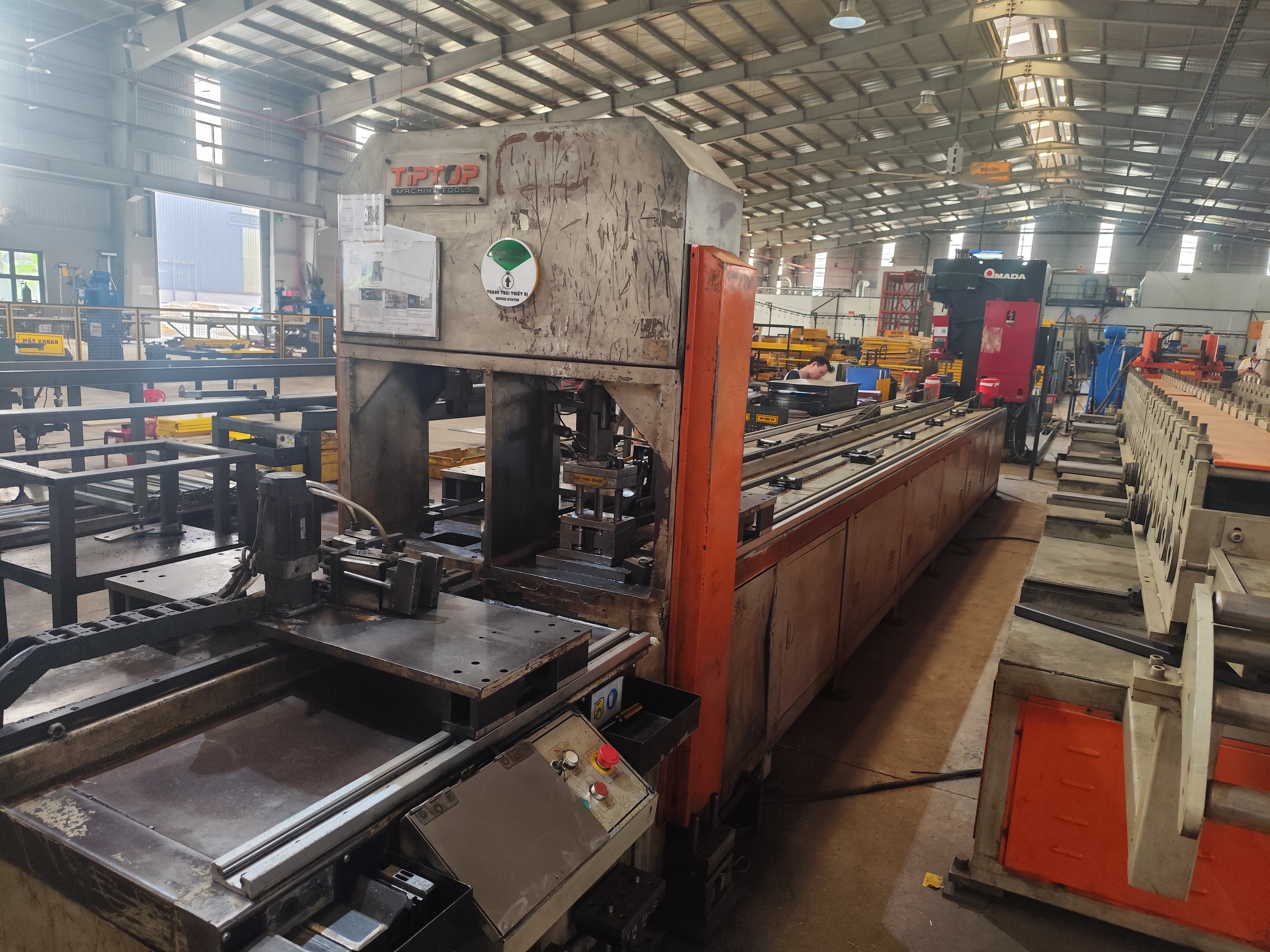

The dimensional tolerance range for stamping parts confuses many buyers I work with. One vague callout on a drawing, and our inspection team catches rejects a supplier never saw coming.
The typical dimensional tolerance range for stamping parts is ±0.005 in to ±0.020 in (±0.13 mm to ±0.5 mm) for standard features. Precision stamping can hold ±0.001 in to ±0.005 in on select features, while formed or multi-bend dimensions may open up to ±0.030 in or more.
That answer is the short version. The real answer depends on the feature, the material, and the process. Let me walk you through how to get this right on your next order.
How Do I Know Which Tolerance Class My Stamping Parts Actually Need?
A few months back, our team in Vietnam reviewed a bracket drawing where every dimension carried ±0.002 in. The buyer only needed that on two hole positions. The rest was wasted money.
Match the tolerance class to each feature's function. Use ±0.001–0.005 in only for critical fits like hole positions or mating surfaces. Apply ±0.005–0.010 in for standard features, and ±0.010–0.030 in for non-critical formed dimensions, bends, and cosmetic edges.

Stamping tolerances are not one number for the whole part. The same bracket can hold very tight hole-to-hole spacing on a flat plane while its bend locations drift much more. So the first question is never "what tolerance can the supplier hold?" It is "what does each feature actually do?"
Start With Function, Not Capability
Ask three simple questions for every dimension. Does this feature mate with another part? Does it locate a fastener? Or does it just define the general shape? Only the first two deserve tight tolerances. When we run DFM reviews with our engineering clients, we often loosen 60 to 70 percent of the callouts on a drawing without touching function.
Typical Tolerance Bands by Feature Type
| Feature Type | Typical Tolerance | Why |
|---|---|---|
| Pierced hole diameter | ±0.002 – ±0.005 in | Punch and die define size directly |
| Hole-to-hole spacing (same plane) | ±0.002 – ±0.005 in | Cut in one die station, very stable |
| Blanked outer profile | ±0.005 – ±0.010 in | Depends on die clearance and wear |
| Single bend location | ±0.005 – ±0.020 in | Springback 1 adds variation |
| Angular bend tolerance | ±0.5° – ±1° | Material temper drives springback |
| Dimension across 2–4 bends | ±0.030 in or wider | Variation stacks with each bend |
Notice the pattern. Anything cut flat is tight. Anything formed is looser. The more a feature depends on material flow or springback, the harder it is to control. Precision numbers like ±0.001 in are real, but they apply to specific small features under controlled conditions, never to every dimension on the part. Specify accordingly and your quotes will drop while your conformance rate rises.
Why Do My Stamping Suppliers in Asia Struggle to Hold Tight Tolerances Consistently?
The first sample lot is rarely the problem. During a supplier audit last year, we found dies still cutting cleanly at kickoff — but with no wear-monitoring plan for the 200,000 pieces that followed.
Suppliers struggle because tolerance capability degrades over time. Die wear after 50,000–100,000 cycles, springback variation between material lots, tolerance stack-up in progressive dies, and inconsistent press control all cause drift. Without SPC and scheduled die maintenance, first-article accuracy does not hold through production.
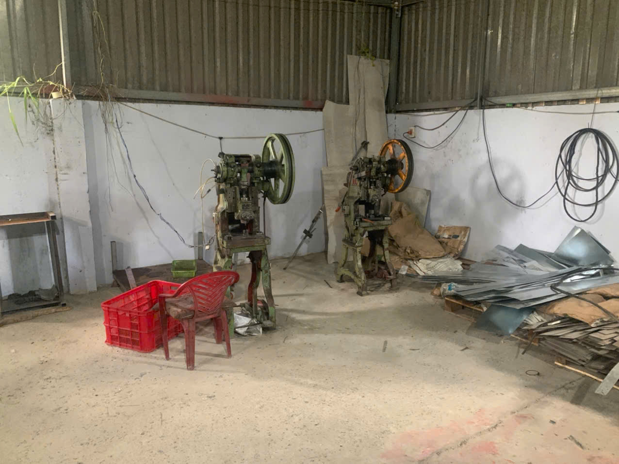
Passing a first-article inspection and holding tolerance across a full production run are two very different achievements. Most tolerance disputes we mediate between U.S. buyers and Asian factories come down to this gap.
The Four Drift Mechanisms
First, die wear. Punches and dies wear progressively. After roughly 50,000 to 100,000 cycles, cutting edges dull and clearances open. Hole sizes grow. Burrs increase. A shop that regrinds on schedule holds tolerance. A shop that waits for rejects does not.
Second, material lot variation. Springback depends on temper and hardness. Two coils of the same grade can behave differently. A bend angle tuned for one coil may miss by a degree on the next. Good suppliers check incoming material certs and adjust. Weak suppliers just run the press.
Third, stack-up in progressive dies 2. Every station adds a little variation. A part passing through eight or more stations can show cumulative deviation two to three times greater than a single-feature tolerance. Only per-station monitoring keeps this in check.
Fourth, press condition. Older mechanical presses have more rebound variation near bottom dead center. Servo presses with programmable ram control improve repeatability noticeably. When we audit factories in Vietnam and Taiwan for our clients, press age and maintenance records are among the first documents we pull.
What Separates Capable Suppliers
| Weak Supplier Behavior | Capable Supplier Behavior |
|---|---|
| Inspects first articles only | Runs in-process SPC on key dimensions |
| Regrinds dies after rejects appear | Schedules die maintenance by cycle count |
| Ignores coil-to-coil variation | Verifies material certs, adjusts setups |
| Quotes tight tolerances without data | Shows Cpk data before committing |
The lesson is simple. Consistency is a system, not a skill. Ask about the system, not just the sample.
What Tolerance Standards Should I Specify to Avoid Non-Conforming Parts?
Drawing ambiguity is the quiet killer of stamping orders. One of our U.S. clients once inherited a drawing with no general tolerance block at all — every supplier quoted against a different assumption.
Specify a recognized general tolerance standard — ISO 2768-1 (medium class) or DIN 6930-2 for stamped sheet metal — as your default, then call out tighter tolerances only on critical features. Add datum references, note post-processing effects, and state which dimensions are measured after plating or heat treatment.
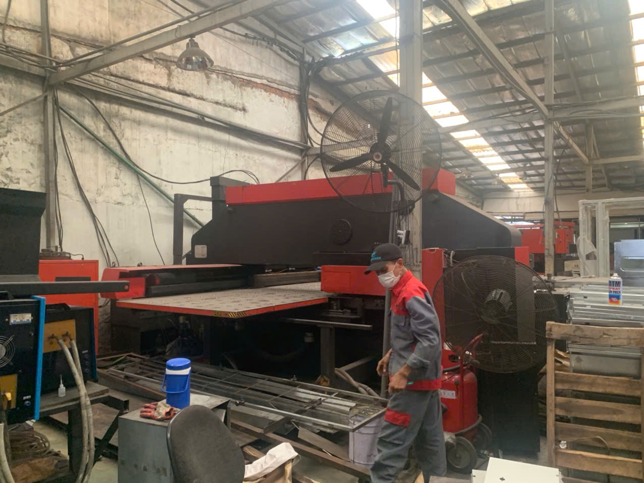
A clean tolerance strategy has two layers. The general tolerance block covers everything you did not call out. The explicit callouts cover the features that matter. Miss either layer and you invite non-conformance.
Choose the Right General Standard
DIN 6930-2 3 was written specifically for stamped sheet-metal parts. It classifies tolerances into grades that respect what stamping can realistically hold. ISO 2768-1 4 is more general but widely understood across Asia. Either works. What fails is writing "±0.005 in unless otherwise specified" on a formed bracket. That blanket number is unrealistic across bends, and it forces suppliers to either quote high or quietly ignore it. Both outcomes hurt you.
A Practical Drawing Checklist
- Add a general tolerance standard and class in the title block.
- Call out tight tolerances only on functional features, with datums.
- Use geometric tolerancing (position, flatness) instead of tight linear dimensions where fit is the real concern.
- Specify bend angle tolerance separately, typically ±1°.
- State the inspection condition: as-stamped, after deburring, or after plating.
- Note that plating, heat treatment, and deburring can shift dimensions by 0.01–0.05 mm, and tolerance the finished state you actually need.
Common Callout Mistakes and Fixes
| Mistake | Consequence | Fix |
|---|---|---|
| Blanket ±0.005 in on all dimensions | High quotes or ignored specs | General standard + selective callouts |
| No datum references | Supplier measures from wrong edge | Define datums on functional surfaces |
| Ignoring plating thickness | Holes undersized after finishing | Tolerance the post-plating dimension |
| No bend angle tolerance | Assembly interference | State ±0.5° to ±1° explicitly |
In our PPAP submissions 5 for U.S. clients, we require the factory to confirm every drawing note in writing before tooling starts. Ambiguity resolved before steel is cut costs nothing. Ambiguity discovered at final inspection costs weeks.
How Can I Verify a Supplier's Real Tolerance Capability Before Placing My Order?
Buyers often ask me how to separate confident quoting from real capability. Every factory says yes to a drawing. Our audit team's job is to find out which ones can prove it.
Verify capability with evidence, not promises. Request capability studies (Cpk ≥ 1.33 on critical dimensions), review calibration records for measuring equipment, run a paid sample or pilot lot with full dimensional reports, audit die maintenance schedules, and confirm SPC is applied in production — not just at first article.

Verification is a sequence, not a single test. Here is the process we follow before recommending any stamping supplier to our clients.
Step 1: Ask for Data Before Samples
Request Cpk or Ppk data 6 from similar past parts. A supplier holding ±0.003 in on comparable material and thickness will have records. A supplier who cannot produce any capability data is guessing. Also ask what standard their gauges are calibrated to and when they were last certified. A tolerance claim is only as good as the instrument measuring it.
Step 2: Audit the Process, Not the Showroom
When our team visits factories in Vietnam or elsewhere in Asia, we look past the polished lobby. We check the die maintenance log against cycle counters. We look for SPC charts posted at the press, filled in by hand or by system, with real dates. We ask the operator — not the sales manager — what happens when a dimension trends toward a limit. The answer tells you everything about the culture.
Step 3: Run a Pilot Lot With Full Reporting
Order a small paid run, not just free samples. Free samples get special treatment. A pilot lot of a few hundred to a few thousand pieces reveals how the process behaves under normal conditions. Require a full dimensional report on parts pulled from the start, middle, and end of the run. Compare the spread, not just the averages.
Step 4: Lock Capability Into the Contract
Define critical dimensions, inspection frequency, and the acceptance method (AQL level 7 or 100 percent check) in the purchase agreement. We handle this stage for clients as part of process control and final inspection, so the expectation is documented before the first coil is loaded. Suppliers respect what is written and measured. They forget what was only discussed.
This sequence takes two to four extra weeks up front. It routinely saves months of rework, returns, and air-freight recovery shipments later.
Conclusion
Stamping tolerances are feature-specific, not part-wide. Specify ±0.005 in only where function demands it, adopt recognized standards, and verify supplier capability with data — before problems reach your dock.
Frequently Asked Questions
How Do I Know Which Tolerance Class My Stamping Parts Actually Need?
A few months back, our team in Vietnam reviewed a bracket drawing where every dimension carried ±0.002 in. The buyer only needed that on two hole positions. The rest was wasted money.
Why Do My Stamping Suppliers in Asia Struggle to Hold Tight Tolerances Consistently?
The first sample lot is rarely the problem. During a supplier audit last year, we found dies still cutting cleanly at kickoff — but with no wear-monitoring plan for the 200,000 pieces that followed.
What Tolerance Standards Should I Specify to Avoid Non-Conforming Parts?
Drawing ambiguity is the quiet killer of stamping orders. One of our U.S. clients once inherited a drawing with no general tolerance block at all — every supplier quoted against a different assumption.
Footnotes
1. Background on the metal-forming phenomenon causing bend tolerance variation. ↩︎
2. Explains progressive die tooling, which causes the tolerance stack-up described. ↩︎
3. DIN is the standards body that authored this sheet-metal tolerance grading system. ↩︎
4. ISO publishes the general tolerance standard referenced for stamped part dimensions. ↩︎
5. AIAG originated PPAP, the automotive quality documentation process referenced here. ↩︎
6. Explains the statistical process capability indices buyers should request from suppliers. ↩︎
7. ASQ defines acceptable quality level sampling standards used in acceptance testing. ↩︎