

The dimensional tolerance range for stamping parts confuses many buyers I work with Production Part Approval Package 1. Vague specs cause rejected shipments, rework, and delays. Our sourcing team sees this problem every month.
The typical dimensional tolerance range for stamping parts is ±0.005 to ±0.010 inches (±0.127 to ±0.254 mm) for most commercial features. Simple pierced holes can hold ±0.002 inches, while bend angles typically hold ±1 degree, and formed dimensions run looser.
But a single number never tells the full story. Let me break down what these ranges mean for your specific project, and how to spec them correctly.
How Do I Know Which Tolerance Class My Stamping Project Actually Needs?
Last year, a U.S. purchasing manager sent our Singapore office a bracket drawing with ±0.001 inch on every dimension. Our engineers flagged it immediately. Only two features actually needed that precision.
Choose your tolerance class by feature function: use ±0.005 inches as the default for general features, tighten to ±0.002 inches only for critical fits like hole positions, and allow ±0.010 inches or more for non-critical edges and formed dimensions.
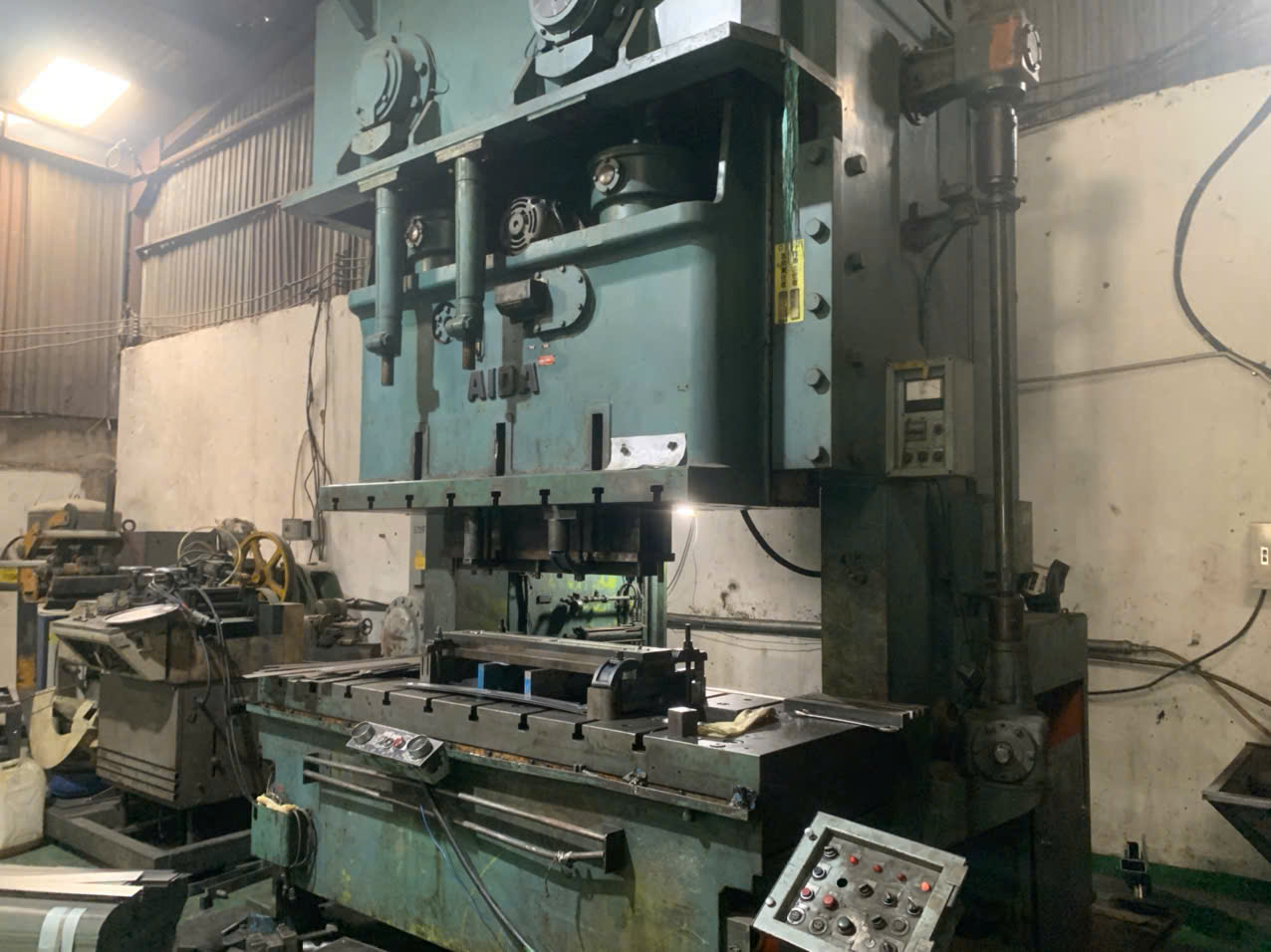
Most buyers over-specify because they fear loose parts. That fear is understandable. But tolerance class should follow function, not fear. Here is the practical logic our project engineers use when we review drawings during OEM co-development.
Match the Tolerance to the Feature Type
Flat features behave differently from formed features. A pierced hole in a flat blank is very repeatable. A dimension that crosses a bend is not. So the first step is to sort your dimensions into categories.
| Feature Type | Typical Achievable Tolerance | When to Tighten |
|---|---|---|
| Pierced hole diameter | ±0.002 to ±0.005 in | Press-fit pins, precision fasteners |
| Hole-to-hole spacing (same plane) | ±0.002 to ±0.003 in | Mating bolt patterns |
| Edge-to-hole distance | ±0.005 in | Locating features |
| Bend angle | ±1° | Spring clips, contact pressure |
| Formed height/depth | ±0.010 to ±0.020 in | Stack-critical assemblies |
| Overall blank profile | ±0.010 to ±0.020 in | Rarely needed tighter |
Ask Three Questions Before Tightening Anything
First, does this feature mate with another part? If yes, it may deserve a tighter callout. Second, will the assembly fail if this dimension drifts by 0.005 inches? If no, leave it at standard. Third, is the feature near a bend? If yes, expect wider variation no matter what the drawing says.
Standards like ISO 2768-1 2 and DIN 6930 give you fine, medium, and coarse grades. Referencing one of these on your title block covers all uncritical dimensions cleanly. Then you only call out the few features that truly matter. In our experience, a well-sorted drawing cuts tooling cost and reduces disputes at final inspection.
What Factors Affect the Achievable Tolerance Range When I Source Stamped Parts from Vietnam or China?
Our Vietnam team audits stamping shops regularly, and the gap between the best and worst facilities is striking. Two shops quoting the same part can differ enormously in real capability.
Achievable stamping tolerances depend on material type and thickness, tooling quality and wear, press repeatability, die design (progressive versus single-stage), springback behavior, and the shop's process control. Well-equipped Asian suppliers routinely hold ±0.05 to ±0.1 mm on linear dimensions.

Geography matters less than capability. I have seen excellent progressive-die shops in northern Vietnam and mediocre ones in coastal China, and the reverse. What matters is the specific supplier's equipment, tooling discipline, and quality system 3. Here are the factors we evaluate during supplier audits.
Material Behavior Drives Variation
Different materials respond differently to piercing and forming. Harder materials wear tooling faster. High-strength steels spring back more after bending. Grain direction affects bend consistency too.
| Material | Typical Piercing Tolerance Capability | Springback Risk |
|---|---|---|
| Mild steel | ~±0.002 in | Low |
| Aluminum | ~±0.002 in | Low to moderate |
| Stainless steel | ~±0.0025 in | Moderate |
| High-strength alloys | ~±0.003 in | High |
Thickness matters as well. Thinner stock, under about 0.5 mm, usually allows tighter control because there is less material flow variability. Thicker gauges introduce more burr, roll-over, and edge draw, which loosens practical tolerances.
Tooling and Process Stability
Progressive dies generally hold tighter, more repeatable tolerances than single-stage or compound processes. Each station does one controlled operation, and the strip is located precisely between stations. But tooling wears. A punch that starts at ±0.002 inches can drift as edges dull. Good shops track tool maintenance schedules and monitor dimensions over the production run, not just at first article.
Springback is the trickiest factor. In high-strength or coated materials, real-world outcomes can shift 0.02 to 0.05 mm beyond the theoretical die design. Capable suppliers compensate through die adjustment or simulation. When we place stamping projects for U.S. clients, we verify these controls during the audit stage, before the purchase order is issued. That single step prevents most tolerance surprises later.
How Can I Verify My Supplier's Claimed Tolerances Through Real Inspection Data?
A buyer once forwarded me a supplier's brochure boasting ±0.001 inch capability. The sample parts told a different story. Marketing claims and measured reality are two separate things.
Verify claimed tolerances by requiring dimensional first-article inspection reports on calibrated equipment, a PPAP package for production parts, capability studies with Cpk of at least 1.33 on critical dimensions, and periodic in-process measurement data across the full production run.

Trust the data, not the datasheet. Any supplier can quote impressive numbers. Only measurement records prove them. Our process control team in Vietnam and China follows a layered verification approach, and you can request the same evidence from any supplier.
The Four Layers of Tolerance Verification
- First Article Inspection (FAI). Every dimension on the drawing gets measured on the first production samples. Ask for the raw measured values, not just pass/fail marks. A report showing 5.08 mm against a 5.00 ±0.10 mm callout tells you the process is running near the edge.
- PPAP documentation. For production programs, a Production Part Approval Package 4 includes dimensional results, material certs, and process flow. We prepare PPAP for our U.S. clients as standard practice on qualified projects.
- Capability studies. A single good sample proves little. A Cpk study across 30 or more parts shows whether the process can hold the tolerance over time. Cpk ≥ 1.33 is the common benchmark for critical dimensions in high-volume stamping.
- In-process and final inspection. Tools wear during a run. Periodic sampling catches drift before it becomes a rejected shipment.
What Good Data Looks Like
| Evidence | What It Proves | Red Flag If Missing |
|---|---|---|
| FAI with actual values | Tool was built correctly | Pass/fail only, no numbers |
| Calibration certificates | Measurements are trustworthy | Uncalibrated calipers only |
| Cpk report on critical dims | Process stays in tolerance | One sample presented as proof |
| Run charts / SPC data | Consistency over volume | No mid-run measurement |
Also check the measurement method itself. A ±0.002 inch feature should be measured on a CMM, optical comparator, or vision system 5. Hand calipers are not adequate for that level. When we run final inspections before shipment, we match the gauge to the tolerance, and we recommend every buyer demand the same.
What Tolerance Mistakes Should I Avoid When Reviewing My Stamping Part Drawings?
Drawing reviews are where our engineers earn their keep. A surprising number of tolerance disputes trace back not to bad manufacturing, but to callouts that were unclear or physically unrealistic from day one.
Avoid these drawing mistakes: over-tolerancing non-critical features, dimensioning formed features from the outside instead of the inside, placing tight tolerances on dimensions that cross bends, ignoring tolerance stack-up in multi-bend parts, and putting holes too close to edges or bend lines.

Each mistake carries a cost. Some raise your piece price. Others create parts that fail inspection even when the supplier did everything right. Let me walk through the ones we flag most often during DFM reviews.
Mistake 1: Over-Tolerancing Everything
Below roughly ±0.02 mm, cost rises steeply. Tight tolerances may require coining, fine blanking, or secondary grinding. If a feature does not need that precision, you are paying for nothing. Start at ±0.005 inches and tighten only where function demands it.
Mistake 2: Dimensioning Formed Features Incorrectly
Formed features should be dimensioned to the inside of the form. The punch controls the inside surface directly. The outside surface varies with material thickness tolerance 6, which you do not control. Drawings dimensioned to the outside invite avoidable disputes.
Mistake 3: Tight Callouts Across Bends
A dimension that spans a bend combines bend angle variation, bend radius variation, and material springback 7. Even a ±1 degree angle tolerance shifts the far end of a long flange noticeably. Keep tight tolerances on same-plane features and give bend-related dimensions realistic room.
Mistake 4: Ignoring Stack-Up in Multi-Bend Parts
Our stepped brackets with multiple 90-degree bends illustrate this well. Each bend adds its own variation. Three bends in series can stack ±1 degree each into a significant end-to-end shift. Use a GD&T datum strategy so tolerances chain from one reference, instead of compounding feature to feature.
Mistake 5: Features Too Close to Edges or Bends
Keep holes at least 1.5 to 2 times material thickness from edges and bend lines. Holes placed closer will distort during forming, and no tolerance callout can fix physics. When we co-develop parts with clients, we catch these issues before tooling is cut, which is far cheaper than fixing them after.
Conclusion
Vague tolerances waste money and cause rejects. The fix is simple: default to ±0.005 inches, tighten only critical features, and demand real inspection data from your supplier.
Frequently Asked Questions
How Do I Know Which Tolerance Class My Stamping Project Actually Needs?
Last year, a U.S. purchasing manager sent our Singapore office a bracket drawing with ±0.001 inch on every dimension. Our engineers flagged it immediately. Only two features actually needed that precision.
What Factors Affect the Achievable Tolerance Range When I Source Stamped Parts from Vietnam or China?
Our Vietnam team audits stamping shops regularly, and the gap between the best and worst facilities is striking. Two shops quoting the same part can differ enormously in real capability.
How Can I Verify My Supplier's Claimed Tolerances Through Real Inspection Data?
A buyer once forwarded me a supplier's brochure boasting ±0.001 inch capability. The sample parts told a different story. Marketing claims and measured reality are two separate things.
Footnotes
1. Explains the PPAP standard referenced for verifying supplier tolerance documentation. ↩︎
2. ISO defines general tolerance grades referenced for uncritical stamped part dimensions. ↩︎
3. ISO 9001 quality management standard underpins supplier quality system evaluation. ↩︎
4. Explains PPAP documentation requirements used to validate stamped production parts. ↩︎
5. Background on vision-based measurement systems used for precise dimensional inspection. ↩︎
6. ASTM sets material specifications and thickness tolerances referenced in stamping design. ↩︎
7. Explains the springback phenomenon that affects bend tolerance accuracy in metal stamping. ↩︎