
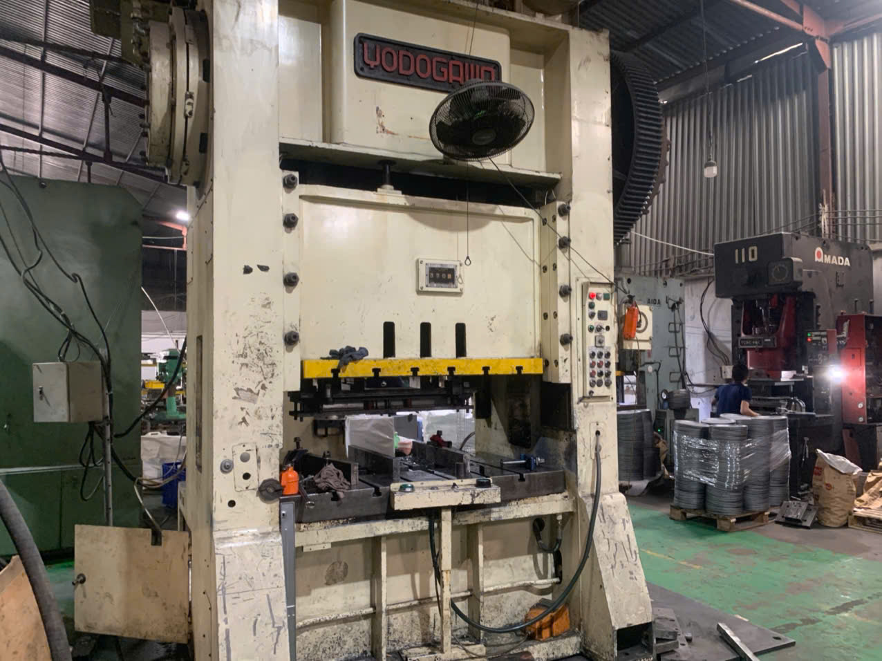
Stamping parts surface roughness questions land in my inbox weekly ISO 4287 1. Buyers over-specify Ra values, pay more, and still get rejected parts. Our sourcing team sees this mistake constantly—and it is avoidable.
The typical required Ra value for stamping parts surface roughness is 1.6 µm. General stamped parts commonly fall between 1.6–3.2 µm Ra, non-critical surfaces accept up to 6.3 µm, and precision sealing, cosmetic, or contact surfaces require 0.8 µm Ra or finer.
That is the short answer. But the right Ra spec for your part depends on function, material, and process ISO 4287 2. Let me walk you through how to get it right.
How Do I Determine the Right Ra Value for My Stamping Part Application?
A U.S. purchasing manager once sent our team a bracket drawing with Ra 0.4 µm on every surface. When I asked why, he admitted the CAD template defaulted to it. That one setting nearly doubled his quote.
Determine the right Ra value by function first: hidden structural surfaces accept Ra 3.2–6.3 µm, general-purpose surfaces need Ra 1.6 µm, visible or mating surfaces need Ra 0.8 µm, and sealing or sliding contact surfaces need Ra 0.4–0.8 µm. Always specify the loosest finish that still works.

Function should always drive the spec. The fact that a part is stamped matters less than what its surfaces actually do. So before you write any Ra number on a drawing, ask four simple questions. What touches this surface? Does it seal against anything? Does anything slide across it? Will a customer see it?
A Function-First Decision Table
Here is the framework we use when reviewing client drawings before quoting:
| Surface Function | Recommended Ra | Why |
|---|---|---|
| Hidden structural (inside an assembly) | 3.2–6.3 µm | No contact or visual requirement; cheapest to produce |
| General-purpose stamped surface | 1.6 µm | Clean finish, good default, no special tooling needed |
| Visible consumer-facing or coated surface | 0.8–1.6 µm | Better appearance; smoother base for plating or paint |
| Mating fit or electrical contact | 0.8 µm | Consistent contact area and predictable fit |
| Sealing or wear-sensitive interface | 0.4–0.8 µm | Prevents leak paths; reduces friction and wear |
Notice the pattern. Most stamped brackets, clips, and mounts sit in the top two rows. Take the mounting brackets we source regularly—stepped zigzag profiles with punched holes for fasteners. They bolt into hidden positions inside cabinets or machinery. For those, Ra 3.2 µm is perfectly fine. Nobody sees them. Nothing slides on them.
The trap is specifying tight Ra "just to be safe." Tighter Ra below 0.8 µm pushes cost up sharply, not gradually. It often forces polished tooling or secondary finishing. If the function does not demand it, you are paying for smoothness that adds zero value. My advice: default to Ra 1.6 µm, loosen to 3.2 µm where you can, and only tighten below 0.8 µm when a real functional need exists.
What Ra Values Should I Specify for Different Stamping Materials and Processes?
Our engineers in Vietnam ran the same progressive die trial on three materials last year. Stainless steel 3 came out noticeably smoother than mild steel under identical press settings. Material choice changes what Ra you can realistically hold.
Specify Ra 1.6–3.2 µm for mild steel stamping, Ra 0.8–1.6 µm for stainless steel and aluminum, and Ra 1.6–6.3 µm for heavy blanking operations. Well-controlled precision stamping with polished dies can achieve Ra 0.4–0.8 µm without secondary finishing.
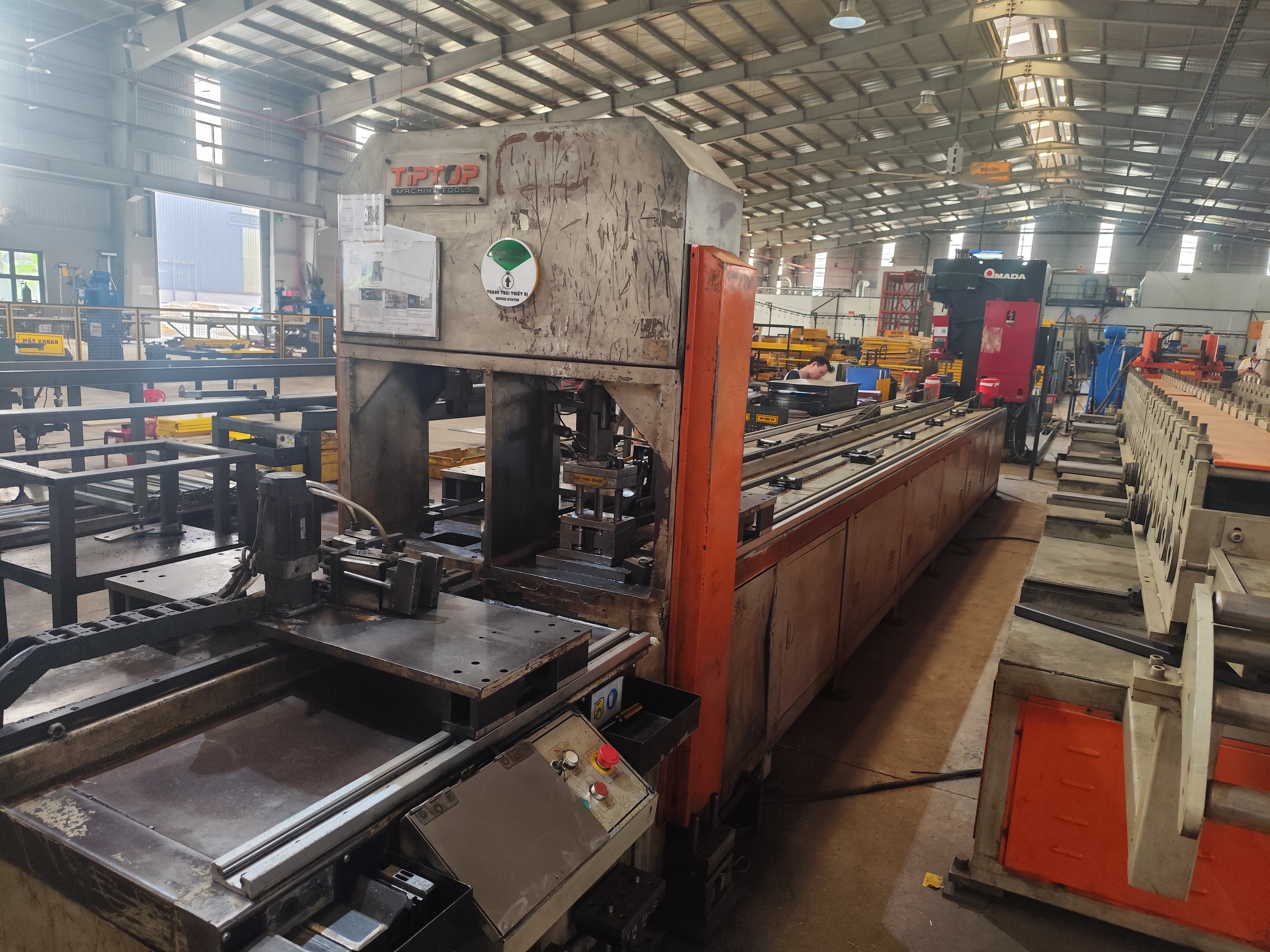
Different materials respond differently to the same die. Stainless steel and aluminum alloys generally produce finer, more consistent finishes than mild or carbon steel under identical conditions. Galvanized steel 4 adds another variable, because the zinc coating has its own surface character before the press ever touches it.
Achievable Ra by Material and Process
| Material / Process | Typical As-Stamped Ra | Achievable with Polished Tooling |
|---|---|---|
| Mild / carbon steel stamping | 1.6–3.2 µm | 0.8–1.6 µm |
| Stainless steel stamping | 0.8–1.6 µm | 0.4–0.8 µm |
| Aluminum alloy stamping | 0.8–1.6 µm | 0.4–0.8 µm |
| Galvanized steel forming | 1.6–3.2 µm | ~1.6 µm (coating limits gains) |
| Heavy blanking / cutting edges | 1.6–6.3 µm | 1.6–3.2 µm |
The Die Transfers Its Finish to Your Part
Here is the principle every buyer should understand. The stamped surface is largely a mirror of the tooling surface. If you need Ra 0.8 µm on the part, the die and punch faces typically need polishing to Ra 0.1–0.4 µm. That is why tight part specs raise tooling cost—the polish lives in the die, not on the part.
Cut edges are a separate story. A sheared or blanked edge is always rougher than the sheet face, often 1.6–6.3 µm with a burr zone. When our clients need smooth edges, we plan for fine blanking 5 or deburring from the start. On your drawing, distinguish face roughness from edge roughness. Many disputes we mediate come from a single Ra callout that the supplier applied to faces while the buyer meant edges too.
Also remember that Ra follows the ISO preferred series: 0.4, 0.8, 1.6, 3.2, 6.3 µm. Stick to these standard values. Odd numbers like Ra 1.2 µm confuse inspection and add no real precision.
How Can I Ensure My Supplier Consistently Meets My Required Ra Tolerance?
Consistency is where most sourcing relationships break down. During a supplier audit in Vietnam, we found a shop whose first-article parts measured Ra 1.4 µm—but parts from the 80,000th stroke measured Ra 2.1 µm. The die had worn, and nobody was tracking it.
Ensure consistent Ra compliance by requiring a PPAP with surface roughness data, defining Ra measurement location and direction on the drawing, setting scheduled die re-polishing intervals, and auditing the supplier's in-process checks. Tool wear typically drifts Ra upward 0.2–0.5 µm over long runs.

Meeting Ra on a first article is easy. Meeting it on part number 200,000 is the real test. Progressive dies wear gradually, and Ra values drift upward by 0.2–0.5 µm over long production runs. A supplier without a re-polishing schedule will ship conforming parts in month one and non-conforming parts in month six—while their paperwork still says everything passed.
Four Controls That Actually Work
In our supply chain projects, we build Ra control around four practical steps:
- Lock the spec at PPAP. Require measured Ra data in the initial sample submission, not just a checkbox. This proves the tooling can hit the target from day one.
- Define measurement conditions on the drawing. State the location, the direction relative to rolling or drawing direction, and the cutoff length. Vague callouts create inspection disputes later.
- Schedule die maintenance by stroke count. Ask the supplier for their re-polishing interval. If they cannot answer, that is a red flag. Good shops re-polish before drift breaches the tolerance, not after.
- Audit in-process checks, not just final inspection. A supplier who measures Ra once per shift catches drift early. One who only checks final lots ships the drift to you.
Process variables matter too. Punch-die clearance, lubrication type, blank holder force, and press speed are the main controllable factors affecting Ra. When we run process control for clients, we ask suppliers to freeze these parameters after PPAP 6 approval. A quiet lubricant change to save cost can shift your surface finish overnight. Change control clauses in the purchase agreement close that gap. Combined with final inspection before shipment, these steps turn "right first time" from a slogan into a repeatable outcome.
What Measurement Methods Should I Use to Verify Surface Roughness on Stamped Parts?
Two inspectors once gave me two different Ra readings on the same bracket—one measured along the grain, one across it. Both were "correct." The drawing simply never said which direction to measure.
Verify surface roughness on stamped parts using a calibrated stylus profilometer per ISO 4287 or ASME B46.1, measuring perpendicular to the lay unless specified otherwise. Use roughness comparison plates for quick shop-floor checks, and always record measurement direction and location.

Measurement sounds simple until two parties disagree. Ra readings differ significantly depending on whether you measure parallel or perpendicular to the stamping or drawing direction. Rolling and forming create a directional texture called lay. Measuring along the lay gives a lower, flattering number. Measuring across it gives a higher, more honest one. If your drawing does not specify direction, your supplier and your incoming inspector may both be right—and still disagree.
Comparing the Main Measurement Methods
| Method | Accuracy | Speed | Best Use Case |
|---|---|---|---|
| Stylus profilometer (portable) | High | Moderate | Formal inspection, PPAP, dispute resolution |
| Benchtop profilometer | Very high | Slow | Lab verification, tight tolerances below 0.8 µm |
| Optical / laser scanner | High | Fast | Non-contact checks on soft or coated surfaces |
| Roughness comparison plates | Low (visual/tactile) | Very fast | Shop-floor spot checks against ISO 1302 7 samples |
Practical Rules We Apply at Final Inspection
First, calibrate. A profilometer that has not been verified against a reference specimen produces numbers nobody should trust. Our inspection protocol requires a calibration check before each lot.
Second, standardize the cutoff length. For Ra values between 0.8 and 3.2 µm, a 0.8 mm cutoff is the common choice. Mixing cutoff lengths between supplier and buyer creates phantom discrepancies.
Third, measure multiple points. One reading tells you almost nothing about a formed part. We take readings at agreed locations—flat flanges, formed walls, and any functional surface—and report each separately. Edges and bends behave differently from flat faces, so a single average hides real problems.
Finally, document everything in the inspection report: instrument, cutoff, direction, and location. When that data travels with the shipment, disputes at receiving almost disappear.
Conclusion
Wrong Ra specs cost money twice—once in tooling, once in rejects. Default to Ra 1.6 µm, tighten only for function, and verify with defined measurement rules. Need help specifying or sourcing stamped parts? Reach out to our team.
Frequently Asked Questions
How Do I Determine the Right Ra Value for My Stamping Part Application?
A U.S. purchasing manager once sent our team a bracket drawing with Ra 0.4 µm on every surface. When I asked why, he admitted the CAD template defaulted to it. That one setting nearly doubled his quote.
What Ra Values Should I Specify for Different Stamping Materials and Processes?
Our engineers in Vietnam ran the same progressive die trial on three materials last year. Stainless steel 3 came out noticeably smoother than mild steel under identical press settings. Material choice changes what Ra you can realistically hold.
How Can I Ensure My Supplier Consistently Meets My Required Ra Tolerance?
Consistency is where most sourcing relationships break down. During a supplier audit in Vietnam, we found a shop whose first-article parts measured Ra 1.4 µm—but parts from the 80,000th stroke measured Ra 2.1 µm. The die had worn, and nobody was tracking it.
Footnotes
1. ISO standard governing surface roughness measurement methods referenced in the article. ↩︎
2. Authoritative ISO standard defining surface texture measurement parameters referenced in the article. ↩︎
3. Background reference on stainless steel material properties discussed in the roughness comparison. ↩︎
4. Background explanation of galvanization relevant to the galvanized steel forming discussion. ↩︎
5. Background concept explaining the fine blanking process mentioned for smoother edges. ↩︎
6. Background concept on the production part approval process used for supplier quality control. ↩︎
7. ISO standard defining surface texture indication and roughness comparison samples cited in the table. ↩︎