When a batch of custom mounting brackets arrived at our U.S. client’s facility with hairline cracks along every fillet weld, the root cause traced back to one thing: no agreed welding strength standard 1 between buyer and supplier.
Welding strength standards for sheet metal fabrication are governed by codes such as AWS D9.1 for nonstructural work and AWS D1.1 or ISO 3834 for structural applications. These standards define joint design, procedure qualification, weld inspection, and minimum tensile strength requirements based on material type, thickness, and welding method.
This article walks through how to pick the right welding code, what tests verify weld strength, how to communicate requirements to overseas suppliers, and what happens when process controls fall short Procedure Qualification Record (PQR) 2. Every section draws on real project experience from our work supporting U.S. purchasing managers who source custom sheet metal parts from Asia.
How do I choose the right AWS or ISO welding standards for my custom sheet metal project?
A purchasing manager we work with in Ohio once asked us why his Vietnamese supplier quoted AWS D1.1 3 for a simple electronics enclosure — it tripled inspection costs for a part that only needed AWS D9.1 4.
Choose AWS D9.1 for nonstructural sheet metal such as enclosures, covers, and brackets under light loads. Use AWS D1.1 or D1.3 for structural steel joints bearing significant loads. Select ISO 3834 when your European or global clients require an internationally recognized quality management framework for welding.
Understanding the Code Landscape
There is no single universal welding strength standard for sheet metal. The right code depends on three things: the function of the part, the material, and where it ships.
AWS D9.1 is the foundational code for nonstructural sheet metal fabrication. It covers arc welding and braze welding of items like ductwork, housings, and light brackets. It includes provisions for welder qualification, workmanship standards, and visual inspection criteria. Most custom sheet metal parts — mounting plates, protective housings, decorative panels — fall under this code.
AWS D1.1 (Structural Welding Code – Steel) and AWS D1.3 (Structural Welding Code – Sheet Steel) apply when the weld carries a structural load. If a bracket supports heavy equipment or a frame bears dynamic forces, these codes govern procedure qualification, filler metal selection, and minimum tensile strength requirements.
ISO 3834 5 is not a product standard. It is a quality management standard for welding. It tells you how a factory should control its welding processes. Many European buyers require ISO 3834 compliance as proof that the supplier has documented procedures, trained welders, and calibrated equipment.
Matching Code to Application
| Application Type | Recommended Standard | Typical Parts | Load Condition |
|---|---|---|---|
| Nonstructural enclosures | AWS D9.1 | Covers, housings, ductwork | Light or no load |
| Structural steel joints | AWS D1.1 / D1.3 | Load-bearing brackets, frames | Significant static or dynamic load |
| Pressure vessels | ASME Section IX | Tanks, vessels | Internal pressure |
| International quality system | ISO 3834 | Any welded part | Varies |
| Automotive sheet metal | AWS D8.1 / ISO 14373 | Body panels, chassis components | Fatigue and crash loads |
A Common Mistake We See
Many suppliers in Asia default to "we follow AWS" without specifying which code. During our supplier audits in Vietnam, we always ask to see the exact welding procedure specification (WPS) 6 and the procedure qualification record (PQR). If the supplier cannot produce these documents, they have not truly qualified their process.
The material properties of your base metal also influence which standard applies. Aluminum sheet metal often requires AWS D1.2 (Structural Welding Code – Aluminum). Stainless steel may need special filler metal matching and shielding gas protocols not covered by D9.1 alone.
When our engineering team reviews a client's drawings, we flag every weld symbol and cross-reference it to the appropriate code. This prevents the supplier from under- or over-specifying the welding requirements — both of which cost money.
Tolerance and Joint Design Standards
For sheet metal thicknesses between 0.5 mm and 6 mm, the prevalent tolerance standard is ISO 2768 7. It defines general tolerances for linear and angular dimensions, which directly affect weld fit-up. Poor fit-up leads to gaps, which lead to burn-through or lack of fusion — two of the most common weld defects in thin-gauge work.
A basic joint design rule: the fillet size should be at least equal to the sheet thickness. A 2 mm sheet gets a 2 mm fillet minimum. Fillets should be symmetrical to distribute stress evenly and reduce residual stress concentration.
What destructive and non-destructive tests should I include in my quality control plan to verify weld strength?
Last year, we managed a project where a client's stainless steel brackets passed visual inspection at the factory in Vietnam but failed tensile strength testing 8 at their receiving lab in Texas. The welds looked clean. The problem was lack of fusion hidden beneath the surface.
A robust quality control plan for sheet metal weld strength should include non-destructive testing methods such as visual inspection (VT), dye penetrant testing (PT), and radiographic testing (RT) for critical joints, plus destructive tests like tensile strength testing, bend tests, and macro-etch examination during procedure qualification and first article inspection.
Non-Destructive Testing (NDT) Methods
Non-destructive testing 9 lets you evaluate weld integrity without destroying the part. Here is how the main methods compare for sheet metal:
| NDT Method | What It Detects | Best For | Limitations |
|---|---|---|---|
| Visual (VT) | Surface cracks, undercut, porosity, incomplete fusion | Every weld, every part | Cannot find subsurface defects |
| Dye Penetrant (PT) | Surface-breaking cracks, porosity | Non-magnetic metals (stainless, aluminum) | Only surface defects; part must be clean |
| Magnetic Particle (MT) | Surface and near-surface cracks | Carbon steel and low-alloy steel | Not usable on non-magnetic materials |
| Radiographic (RT) | Internal porosity, inclusions, lack of fusion | Critical structural welds | Expensive; requires certified technicians |
| Ultrasonic (UT) | Internal defects, lack of fusion | Thicker sections (typically > 5 mm) | Difficult on very thin sheet metal |
For most custom sheet metal work in the 0.5–3 mm range, visual inspection is the baseline. Every weld on every part should receive VT. Dye penetrant testing is the next step up and is especially useful for stainless steel and aluminum parts where you cannot use magnetic particle testing.
Radiographic testing is reserved for the most critical joints — those bearing significant loads or operating in safety-critical environments. It is costly and slow, so we only recommend it when the application demands it.
Destructive Testing Methods
Destructive tests are performed during procedure qualification and first article inspection. They are not done on every production part. They confirm that the welding procedure specification (WPS) produces joints meeting the required tensile strength and ductility.
Common destructive tests include:
- Tensile test: Pulls the welded joint apart to measure ultimate tensile strength. The weld must meet or exceed the base metal's minimum tensile strength.
- Bend test: Bends the welded specimen to a specified angle to check for cracks or lack of fusion in the weld and heat affected zone.
- Macro-etch examination: Cross-sections the weld, etches it with acid, and examines under magnification for porosity, incomplete penetration, and fusion defects.
- Nick-break test: Breaks the weld to expose the internal fracture surface for visual evaluation of defects.
Building Your Inspection Plan
When we help clients build a quality control plan, we layer these tests based on risk:
- Every part: 100% visual inspection against the drawing and weld symbol requirements.
- Sampling: Dye penetrant testing on a defined sample size (e.g., AQL-based sampling per lot).
- First article: Full destructive testing during procedure qualification and first article production.
- Periodic re-validation: Destructive test coupons welded at the start of each production shift or batch.
This layered approach catches surface weld defects early and confirms that the process has not drifted from the qualified parameters.
Heat Affected Zone Considerations
The heat affected zone (HAZ) 10 is the area of base metal next to the weld that has been altered by heat but not melted. In thin sheet metal, the HAZ can be a significant portion of the joint width. TIG welding typically produces a smaller HAZ than MIG. Laser welding produces the smallest.
If your part operates under fatigue loading — repeated stress cycles — the HAZ is often where cracks initiate. Your quality control plan should include inspection of the HAZ, not just the weld bead itself. Dye penetrant testing is effective for detecting HAZ cracking in stainless steel and aluminum.
How can I ensure my overseas supplier understands the critical strength requirements on my engineering drawings?
On one of our projects last year, a supplier in China misread a weld-all-around symbol as a stitch weld call-out. The result was a batch of mounting brackets with intermittent welds where continuous seams were required — and every unit failed the client's incoming load test.
Ensure your overseas supplier understands critical weld strength requirements by using standardized AWS weld symbols on drawings, providing a written welding procedure specification (WPS), holding a pre-production DFM review meeting, requiring first article inspection with documented test results, and confirming the supplier has qualified welders per the applicable code.
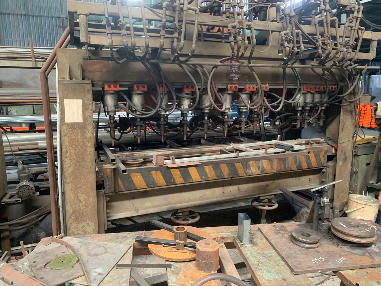
Why Miscommunication Happens
Engineering drawings are a universal language — in theory. In practice, differences in training, regional standards, and shop floor culture create gaps. A weld symbol that is obvious to a U.S. engineer may be unfamiliar to a welder in Southeast Asia trained on a different standard system.
The most common breakdowns we encounter:
- Weld symbol interpretation errors: Confusing fillet size with throat size, or missing the "weld all around" flag.
- Missing or vague notes: Drawings that state "weld per AWS" without specifying which AWS code.
- No WPS provided: The supplier welds based on operator experience rather than a documented procedure.
- Material callout ambiguity: Not specifying the exact grade of stainless steel or aluminum alloy, which affects filler metal selection and material properties.
The DFM Review Process
At our offices in Vietnam and China, we run a Design for Manufacturing (DFM) review before any welding begins. This review is a structured meeting — not a casual email exchange. Here is what we cover:
- Drawing walkthrough: Every weld symbol is reviewed with the welding supervisor and quality engineer.
- WPS confirmation: We verify the supplier has a documented WPS for the specific material, thickness, and joint type. If not, we require them to create and qualify one.
- Filler metal and shielding gas review: We confirm the filler metal matches the base material and the shielding gas is appropriate (e.g., argon for TIG on stainless steel, argon-CO₂ mix for MIG on carbon steel).
- Parameter lock-down: Amperage, travel speed, and number of passes are documented. For thin sheet metal (0.5–3 mm), low amperage and multi-pass strategies prevent burn-through and excessive residual stress.
- Inspection criteria agreement: We define the accept/reject criteria for weld defects — maximum porosity size, allowable undercut depth, surface finish requirements.
Welding Method Selection and Strength Comparison
Part of the DFM review involves confirming the right welding method for the application. Not all methods produce the same strength.
| Welding Method | Relative Strength | Best For (Sheet Metal) | Min. Thickness | Typical Amperage / Power |
|---|---|---|---|---|
| TIG (GTAW) | Very High | Thin gauges, visible seams, precision | 0.5 mm | 20–70 A |
| MIG (GMAW) | High | Moderate thickness, production speed | 0.8 mm | 30–90 A |
| Laser Welding | Very High | Ultra-thin panels, electronics, medical | 0.3 mm | 400–800 W |
| Spot Welding (RSW) | Moderate | Lap joints, high-volume production | 0.4 mm | 4–8 kA |
| Pulse MIG/TIG | High | Thin materials, reduced heat input | 0.5 mm | 20–60 A |
| Stitch Welding | Moderate | Cost-balance, non-critical joints | 0.8 mm | Varies |
| Tack Welding | Temporary Only | Fixturing before final welding | N/A | Low |
We share this table with clients during the quoting phase so they understand why we recommend TIG for a visible bracket versus spot welding for a high-volume internal component. The joint design, heat affected zone size, and distortion risk all change with the method.
Translating Requirements Into Supplier Action
Beyond the DFM review, we use three practical tools:
- Bilingual WPS documents: We translate key welding parameters and accept/reject criteria into the supplier's working language.
- Reference photos: We provide photos of acceptable and unacceptable welds — visual standards that bridge any language gap.
- First article inspection (FAI): Before production ramps up, we require the supplier to produce sample parts. These parts undergo full dimensional inspection and, where required, destructive testing. Only after FAI approval does production begin.
This process takes time up front. But it eliminates the far more expensive cost of rework, returns, and supply chain delays later.
What are the risks to my supply chain if my manufacturer lacks certified welding process controls?
We learned this lesson the hard way on a project three years ago. A supplier quoted an aggressive price on a batch of charcoal-gray powder-coated mounting brackets. They had welding equipment. They had experienced operators. What they did not have was procedure qualification records, documented WPS documents, or a system for tracking welder certifications.
Without certified welding process controls — including qualified WPS documents, welder certifications, and documented inspection procedures — your supply chain faces risks of inconsistent weld quality, hidden defects, batch rejections, delivery delays, product liability exposure, and loss of end-customer confidence.
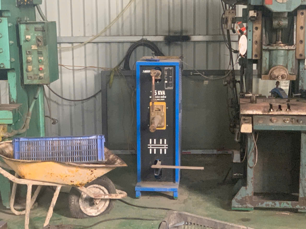
The Cascade of Failures
When a supplier lacks process controls, problems do not appear one at a time. They cascade.
First, the welding parameters drift. Without a locked-down WPS, each operator welds at their own preferred amperage and speed. One operator runs too hot, causing burn-through and distortion. Another runs too cold, producing lack of fusion. Both defects compromise tensile strength.
Second, there is no early detection. Without a documented inspection plan, weld defects pass through unchecked. Parts reach your receiving dock looking acceptable on the outside but hiding porosity or incomplete penetration inside.
Third, when defects are discovered — usually by your end customer — the entire batch is suspect. You face a containment action, a sorting exercise, and potentially a recall. Delivery timelines collapse.
What Certified Process Controls Look Like
A properly controlled welding operation includes these elements:
- Welding Procedure Specification (WPS): A document that defines the exact parameters — material, joint type, filler metal, shielding gas, amperage, travel speed, preheat, interpass temperature.
- Procedure Qualification Record (PQR): Test results from destructive testing of coupons welded per the WPS. This proves the procedure produces sound welds.
- Welder Performance Qualification (WPQ): Records showing each welder has passed a qualification test for the specific process and position they will perform.
- Inspection and test plan (ITP): Defines what non-destructive testing and dimensional checks are performed, at what frequency, and what the accept/reject criteria are.
- Traceability: Material certificates, filler metal lot numbers, and welder identification are recorded for each production lot.
The Cost of Getting It Wrong vs. Getting It Right
Many purchasing managers compare supplier quotes on unit price alone. The supplier with certified process controls often quotes higher. But the total cost of quality tells a different story.
Consider a batch of 500 custom brackets. If 15% fail incoming inspection due to weld defects, you face sorting costs, rework or replacement costs, expedited freight for replacement parts, and production downtime at your client's facility. That 15% failure rate can easily add 30–40% to the effective unit cost — far exceeding the price premium of a qualified supplier.
Emerging Technologies Strengthening Process Control
Smart robotics and AI-driven welding systems are gaining traction in high-volume sheet metal fabrication. These systems use real-time monitoring sensors to track arc voltage, current, wire feed speed, and travel speed. They compare live data against the WPS parameters and flag deviations instantly.
IoT-connected welding equipment enables digitalization of quality records. Every weld on every part can be logged with its actual parameters, creating a digital traceability record. This is especially valuable for safety-critical applications in automotive, medical, and aerospace sectors.
Even in factories that use manual welding, simple digital tools — tablets with photo documentation, barcode-linked WPS access, and electronic inspection checklists — dramatically improve consistency and reduce the risk of operator error.
Sustainability is also entering the conversation. Low-emission welding techniques and energy-efficient inverter-based welding equipment reduce environmental impact while often improving arc stability and control on thin materials. Clients exporting to Europe increasingly ask about their supply chain's environmental practices, and welding process controls are part of that picture.
Conclusion
Welding strength standards for sheet metal fabrication are not optional — they are the foundation of reliable parts. Choose the right code, test rigorously, communicate clearly with suppliers, and demand certified process controls to protect your supply chain.
Frequently Asked Questions
How do I choose the right AWS or ISO welding standards for my custom sheet metal project?
A purchasing manager we work with in Ohio once asked us why his Vietnamese supplier quoted AWS D1.1 3 for a simple electronics enclosure — it tripled inspection costs for a part that only needed AWS D9.1 4 .
What destructive and non-destructive tests should I include in my quality control plan to verify weld strength?
Last year, we managed a project where a client's stainless steel brackets passed visual inspection at the factory in Vietnam but failed tensile strength testing 8 at their receiving lab in Texas. The welds looked clean. The problem was lack of fusion hidden beneath the surface.
How can I ensure my overseas supplier understands the critical strength requirements on my engineering drawings?
On one of our projects last year, a supplier in China misread a weld-all-around symbol as a stitch weld call-out. The result was a batch of mounting brackets with intermittent welds where continuous seams were required — and every unit failed the client's incoming load test.
Footnotes
1. Explains the importance of proper specifications to prevent weld failure. ↩︎
2. Replaced HTTP 404 with an authoritative online course overview from the American Welding Society explaining Procedure Qualification Records (PQR), often discussed alongside WPS. ↩︎
3. Replaced HTTP 403 with the official AWS D1.1/D1.1M:2025-AMD1 Structural Welding Code – Steel page from the American Welding Society. ↩︎
4. Describes AWS D9.1 as the standard for thin-gauge sheet metal welding. ↩︎
5. Defines ISO 3834 as an international quality management system for fusion welding. ↩︎
6. Replaced HTTP 404 with an authoritative online course overview from the American Welding Society explaining Welding Procedure Specifications (WPS). ↩︎
7. Explains ISO 2768 as an international standard for general tolerances in engineering drawings. ↩︎
8. Describes tensile strength testing as a method to ensure durability and compliance. ↩︎
9. Provides a comprehensive overview of non-destructive testing techniques. ↩︎
10. Defines the area of base metal altered by welding heat. ↩︎