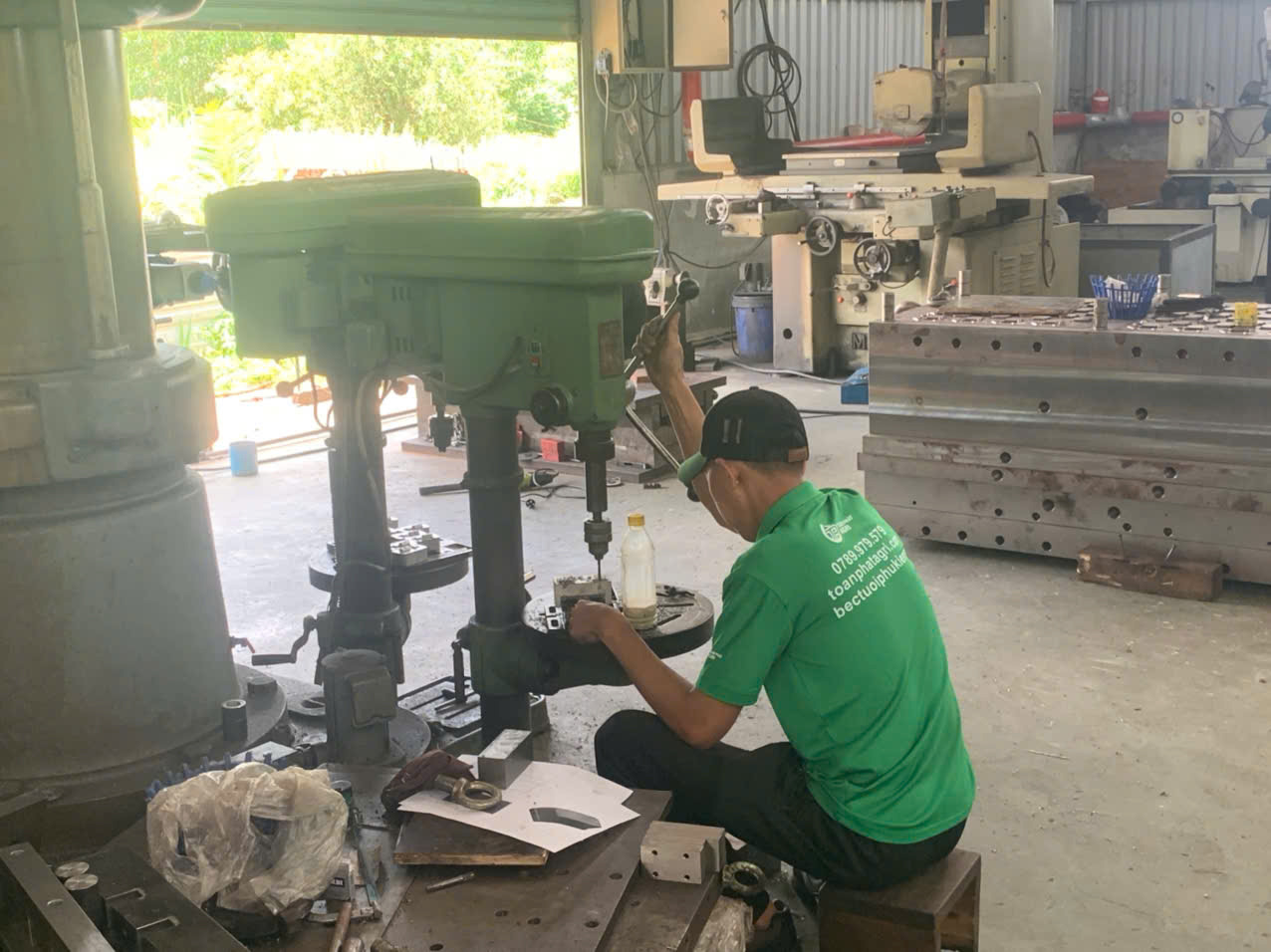
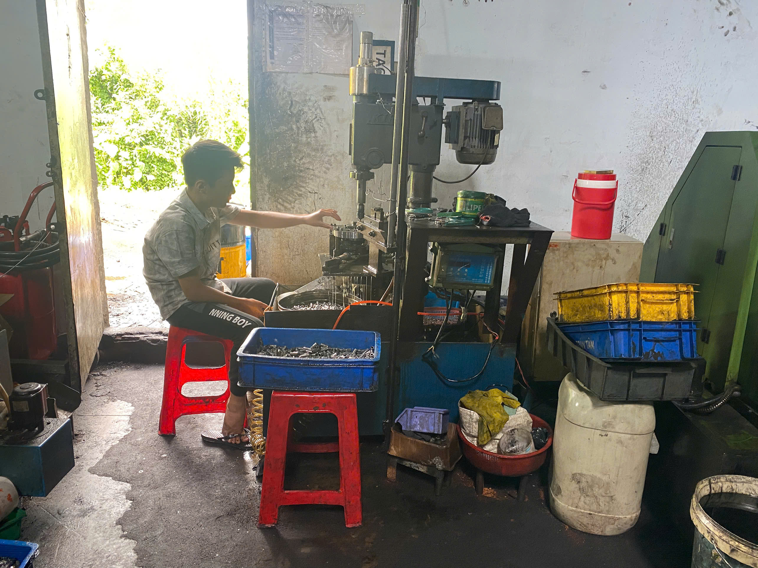
Last quarter, a client’s engineer sent us a 3D model with six different bend angles and asked if we could hold ±0.1 mm across all of them — that conversation taught us a lot about how deeply the working principle of sheet metal fabrication shapes every project outcome digital CAD blueprints 1.
The working principle of sheet metal fabrication relies on applying controlled mechanical force to flat metal sheets — cutting, forming, joining, and finishing them into precise three-dimensional components without compromising material integrity, guided by digital CAD blueprints and strict process controls throughout every stage.
Every step in this sequence matters. Miss one detail in cutting, and your forming tolerances drift. Skip a quality gate after bending, and your assembly won’t fit. Below, I’ll walk you through how this principle applies to real projects, what stages deserve your closest attention, how tolerances are affected, and how to pick the right material.
How Does the Working Principle of Sheet Metal Fabrication Apply to My Project?
A buyer we work with in the Midwest once assumed sheet metal forming was just “cut and bend.” His first prototype came back from another supplier with warped flanges and misaligned holes — because nobody mapped the fabrication principle to his specific part geometry.
The fabrication principle applies to your project by dictating the exact sequence of cutting, forming, and joining operations your part requires. Each operation must be planned around your part’s geometry, material properties, and tolerance needs to avoid rework and ensure right-first-time results.
Why Sequence Matters More Than You Think
Sheet metal fabrication is not a single action. It is a chain of dependent steps. The output of one step becomes the input of the next. If your laser cutting is off by 0.2 mm, your bend line shifts. If your bend line shifts, your weld joint gaps change. If your weld gaps change, your final assembly fails inspection.
When we co-develop a part with a client, the first thing our engineering team does is map the fabrication sequence against the CAD model. We ask: What gets cut first? Where do the bends go? Which edges get welded? This mapping is what turns a flat drawing into a buildable plan.
The Four Core Operations
Here is how the principle breaks down into actionable stages for any project:
| Operation | What Happens | Key Equipment | Typical Tolerance |
|---|---|---|---|
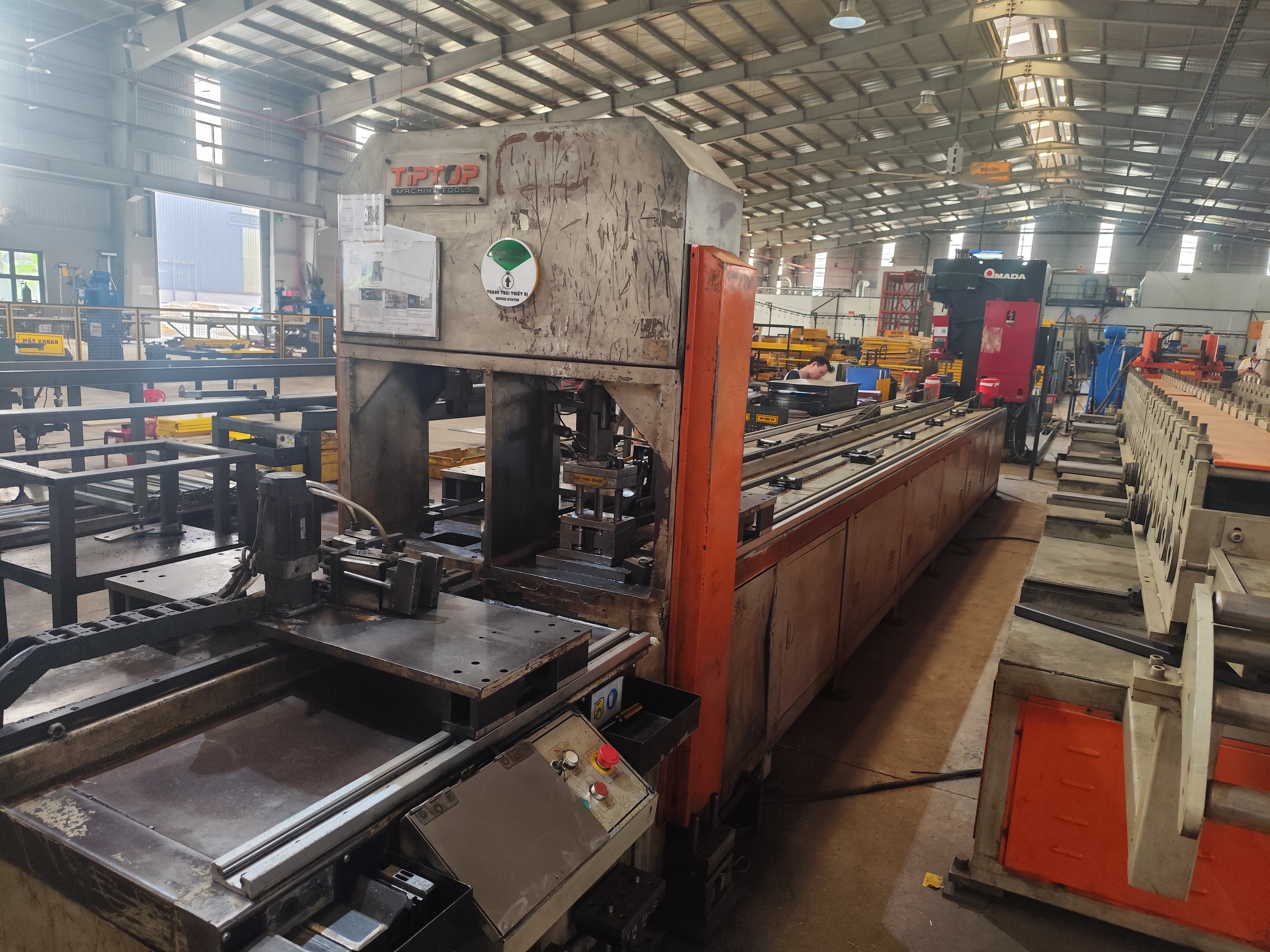
| Cutting | Flat sheet is cut to a 2D profile | Laser cutter, CNC turret punch 2, shear | ±0.05–0.1 mm (laser) |
| Forming | 2D blank is bent or shaped into 3D | Press brake 3, roll former, stamping press | ±0.1–0.3 mm |
| Joining | Separate pieces are assembled | TIG/MIG welder, rivet gun, adhesive | ±0.2–0.5 mm |
| Finishing | Surface is treated for function and appearance | Deburring tool, plating line, paint booth | Visual + functional spec |
Each row in that table is a quality gate. When we manage a project from our Vietnam office, we assign an inspector to each transition point. That is how we catch drift before it compounds.
Matching the Principle to Your Part
Not every part needs all four operations. A simple bracket might only need cutting and bending. A complex enclosure might need laser cutting, multiple bends on a press brake, spot welding, and powder coating. The principle stays the same — controlled force, planned sequence, verified output — but the application changes with your design.
One lesson we learned early: the more bends a part has, the more critical the flat-pattern layout becomes. A flat pattern is the unfolded version of your 3D part. If the flat pattern is wrong, every downstream operation inherits that error. Our engineers use CAD software to calculate bend allowances before we even quote a job.
CNC fabrication has made this mapping faster and more repeatable. Digital files go straight from your design software to the cutting machine. But the human review step — checking that the digital plan matches the physical reality of the material — remains essential.
What Are the Essential Stages I Should Monitor in My Fabrication Workflow?
During a recent PPAP review for a U.S. client, we discovered that a sub-supplier had skipped in-process measurement after the punching operations — and three batches of brackets had oversized holes that nobody caught until final assembly.
The essential stages to monitor are incoming material verification, cutting accuracy, bend angle and dimension checks after forming, weld or joint integrity after assembly, and surface quality after finishing. Each stage needs documented inspection criteria tied to your drawing specifications.
Stage 1: Incoming Material Inspection
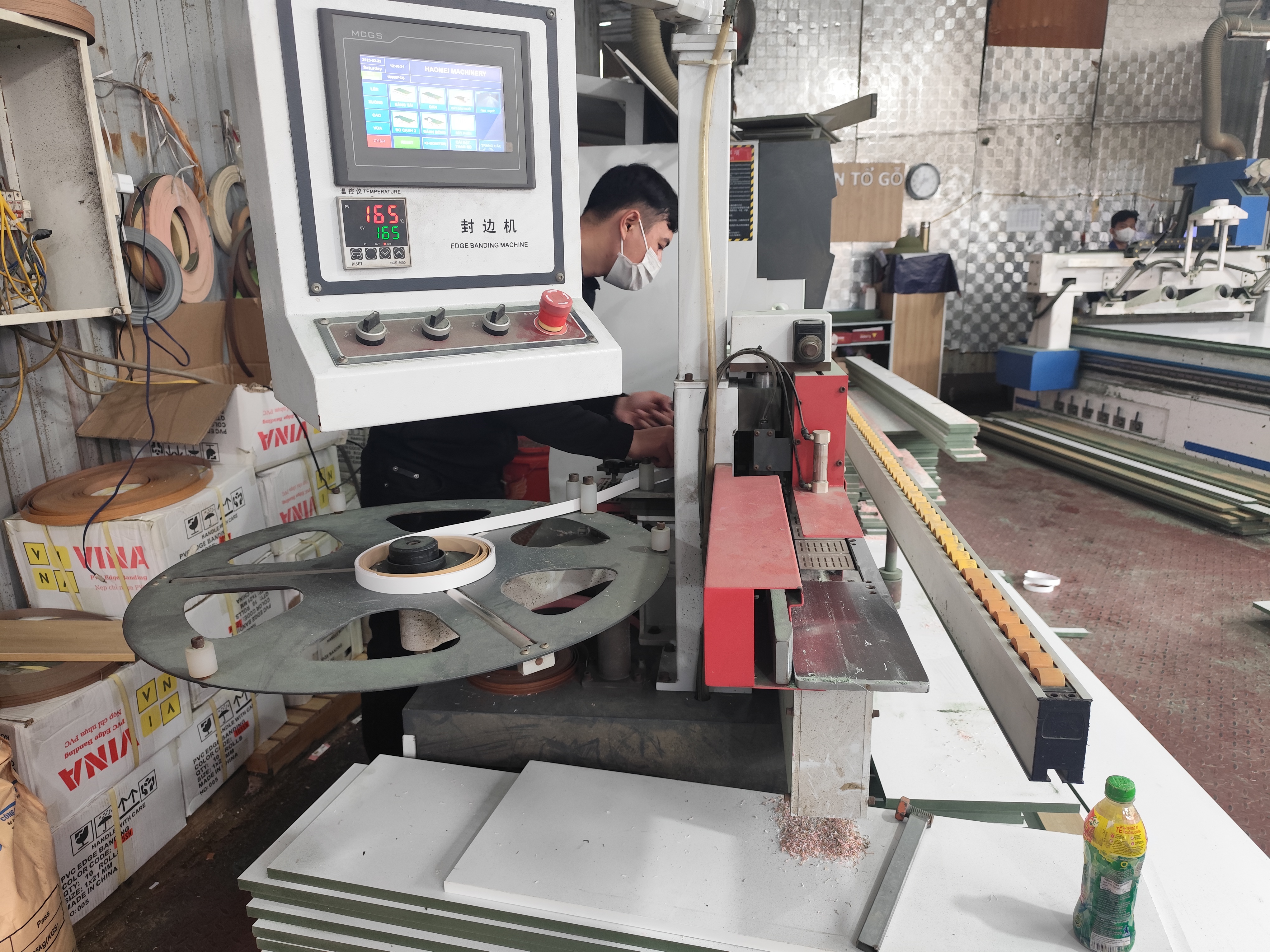
Before any cutting happens, you need to verify the raw sheet. This means checking material grade, thickness, and surface condition. A 0.05 mm deviation in sheet thickness can change your bend results. Our team in Vietnam uses calipers and material certificates to confirm every incoming coil or sheet matches the purchase order.
Stage 2: Cutting Verification
Whether you use laser cutting, shearing metal with a guillotine, or punching operations on a CNC turret, the first pieces off the machine need measurement. We check critical dimensions against the flat-pattern drawing. For laser-cut parts, we also inspect edge quality — looking for excessive burr, heat-affected zones, or taper.
| Cutting Method | Best For | Edge Quality | Speed |
|---|---|---|---|
| Laser cutting | Complex profiles, tight tolerances | Excellent, minimal burr | Medium–High |
| Shearing | Straight cuts, high volume | Good, slight rollover | High |
| Punching | Holes, repetitive features | Good, some burr on exit side | High |
| Waterjet | Thick material, heat-sensitive alloys | Very clean, no heat zone | Low–Medium |
Stage 3: Forming Inspection
Metal bending is where most dimensional problems appear. After each bend on the press brake, the operator should check the bend angle with a protractor or digital angle gauge and measure the flange length. Springback 4 — the tendency of metal to partially return to its original shape after bending — is the main variable here. Different materials spring back different amounts. Aluminum springs back more than mild steel. Our process control sheets list the expected springback offset for each material and thickness combination so operators can compensate.
Stage 4: Joining and Assembly Check
If your part involves welding techniques like TIG or MIG, or mechanical fasteners like rivets, this stage verifies joint strength and alignment. We use go/no-go gauges for hole alignment and visual inspection standards for weld bead quality. For critical welds, destructive testing on sample pieces confirms penetration depth.
Stage 5: Finishing and Final Inspection
Deburring, plating, painting, or annealing — whatever your spec calls for — gets its own check. We run a final dimensional inspection on a sample basis (or 100% for critical parts) and compare against the original drawing. The goal is simple: ship only parts that match the print.
How Does the Fabrication Principle Affect the Final Tolerances of My Components?
A trade-off we weigh on nearly every quote is this: the client wants ±0.1 mm on a formed dimension, but the material is 3 mm aluminum — and the part has four sequential bends. Each bend introduces its own small deviation. The fabrication principle directly governs whether that tolerance target is realistic.
The fabrication principle affects final tolerances because each operation — cutting, forming, and joining — adds its own dimensional variation. Tolerances stack across operations, so tighter control at each stage and fewer total operations yield more precise final components.
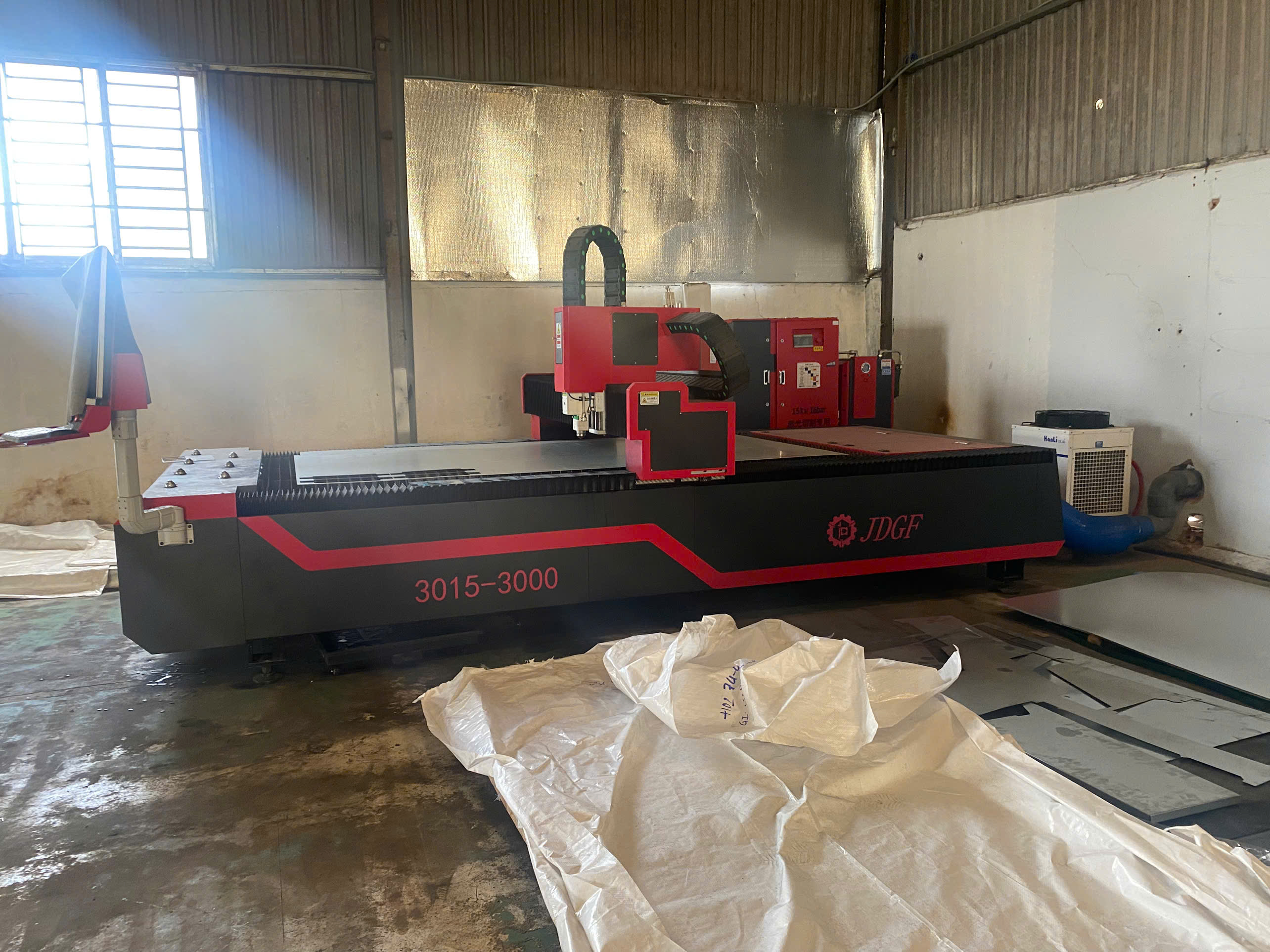
How Tolerance Stacking Works
Think of it like a chain. Each link adds a small amount of slack. In sheet metal fabrication, each operation is a link. Laser cutting might hold ±0.05 mm. A single bend might hold ±0.15 mm. A weld fixture might add ±0.2 mm. If your part goes through all three, the worst-case stack is ±0.4 mm on a dimension that spans all operations.
This is why our engineers push back — respectfully — when a drawing calls for ±0.1 mm on a dimension that crosses two bends and a weld. It is not that we cannot try. It is that the physics of sheet metal forming make it statistically unlikely without special fixturing, which adds cost.
The K-Factor and Bend Accuracy
The K-factor 5 is a ratio that describes where the neutral axis sits within the material thickness during a bend. It typically ranges from 0.3 to 0.5, with 0.4468 being a common average used in calculations. This number matters because it determines the bend allowance — the amount of material consumed by the bend. Get the K-factor wrong, and your flange lengths will be off.
| Material | Typical K-Factor | Springback Tendency | Notes |
|---|---|---|---|
| Mild Steel | 0.40–0.45 | Low–Medium | Most predictable for bending |
| Stainless Steel | 0.42–0.48 | Medium–High | Work hardens; needs more force |
| Aluminum 5052 6 | 0.35–0.42 | High | Cracks if bend radius is too tight |
| Copper | 0.38–0.44 | Low | Soft; easy to form but scratches easily |
Design Choices That Improve Tolerances
There are practical steps you can take at the design stage to keep tolerances achievable:
- Keep bend radii consistent. Using the same inside radius across all bends lets the operator use one tool, reducing setup variation.
- Set the inside bend radius equal to or greater than the material thickness. Going below this risks cracking and distortion.
- Minimize the number of operations. Fewer steps mean fewer sources of variation.
- Use datum features. Locate critical dimensions from a single reference edge or hole so that tolerance stack is controlled.
- Specify GD&T where it matters. Geometric Dimensioning and Tolerancing 7 lets you define which dimensions are critical and which can float.
When we run a deep drawing process or a metal stamping operation for higher volumes, the hard tooling itself becomes the tolerance control. The die geometry is fixed, so part-to-part variation drops significantly. But the upfront tooling cost is higher, so this approach makes sense only when volumes justify it.
Finite Element Analysis (FEA) simulation software 8 can predict how a sheet will behave during forming — where it will thin, where it will wrinkle, where springback will be worst. We use simulation results to adjust tool designs before cutting steel for dies, which reduces the number of physical tryout iterations.
How Do I Choose the Right Material for My Sheet Metal Fabrication Requirements?
One interaction that sticks with me: a client specified 304 stainless steel for an indoor electrical enclosure. When we asked why, the answer was “that’s what we’ve always used.” We suggested powder-coated cold-rolled steel instead — it met the corrosion spec, bent more predictably, and cut the material cost by nearly 40%.
Choose your material by balancing strength, formability, corrosion resistance, weight, conductivity, and cost against your part’s functional requirements and operating environment. Common choices include mild steel for general use, aluminum for lightweight needs, and stainless steel for corrosion-critical applications.
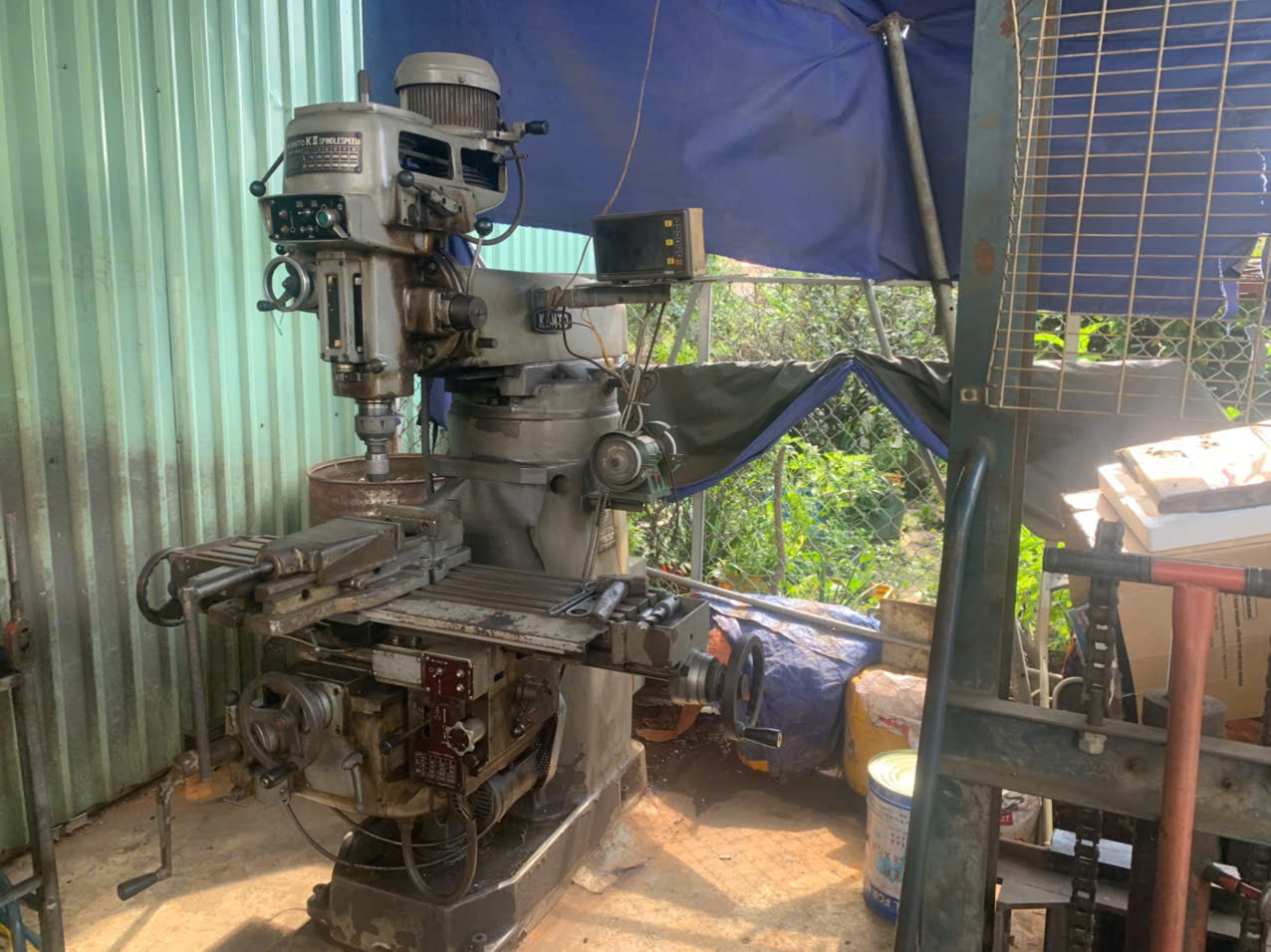
Material Properties You Should Evaluate
Every material behaves differently under the mechanical forces of fabrication. Ductility determines how far you can bend or draw it before it cracks. Yield strength tells you how much force the press brake needs. Thermal conductivity affects how it responds to laser cutting and welding techniques. Here is a comparison of the most common sheet metals:
| Property | Mild Steel (CR) | Aluminum 5052 | 304 Stainless | Copper C110 |
|---|---|---|---|---|
| Density (g/cm³) | 7.85 | 2.68 | 8.00 | 8.94 |
| Yield Strength (MPa) | 200–350 | 195–260 | 205–310 | 70–220 |
| Formability | Excellent | Good | Good | Excellent |
| Corrosion Resistance | Low (needs coating) | Good (natural oxide) | Excellent | Good |
| Weldability | Excellent | Moderate | Good | Moderate |
| Relative Cost | Low | Medium | High | High |
How Operating Environment Drives the Decision
If the part lives outdoors or in a washdown environment, corrosion resistance jumps to the top of the priority list. Stainless steel or aluminum are the usual picks. If the part is structural and stays indoors, mild steel with a protective finish is often the most cost-effective route.
For electronics enclosures that need EMI shielding, copper or nickel-plated steel may be required. For aerospace brackets where every gram matters, aluminum or titanium enters the conversation. The material choice is never just about the metal itself — it is about what the part must do in service.
Formability and Fabrication Compatibility
Not all materials respond the same way to every fabrication process. Aluminum is easy to laser cut but tricky to weld without distortion. Stainless steel work-hardens during bending, so it needs more press brake tonnage and careful springback compensation. Copper is soft and forms beautifully but scratches during handling, so it demands careful surface protection throughout the workflow.
The hydroforming process 9 works well with aluminum and some stainless grades because it applies uniform fluid pressure, reducing localized thinning. Metal stamping with hard tooling suits materials that behave consistently across large production runs — mild steel and certain aluminum alloys are the most predictable here.
Cost vs. Performance: A Practical Framework
We advise clients to start with the cheapest material that meets the functional spec, then move up only if testing or analysis shows a gap. Over-specifying material is one of the most common sources of unnecessary cost in custom parts. A simple decision tree helps:
- Does the part need corrosion resistance without coatings? → Stainless or aluminum.
- Is weight critical? → Aluminum or advanced alloys.
- Is electrical conductivity required? → Copper or brass.
- Is none of the above true? → Start with mild steel and add a finish.
Our team reviews material selection during the co-development phase, before any tooling or programming begins. Changing material after production starts is expensive. Changing it during design review costs nothing but a conversation.
Conclusion
The working principle of sheet metal fabrication is a controlled sequence of cutting, forming, joining, and finishing — and understanding it helps you make smarter decisions on tolerances, materials, and quality control from day one.
Frequently Asked Questions
How Does the Working Principle of Sheet Metal Fabrication Apply to My Project?
A buyer we work with in the Midwest once assumed sheet metal forming was just "cut and bend." His first prototype came back from another supplier with warped flanges and misaligned holes — because nobody mapped the fabrication principle to his specific part geometry.
What Are the Essential Stages I Should Monitor in My Fabrication Workflow?
During a recent PPAP review for a U.S. client, we discovered that a sub-supplier had skipped in-process measurement after the punching operations — and three batches of brackets had oversized holes that nobody caught until final assembly.
How Does the Fabrication Principle Affect the Final Tolerances of My Components?
A trade-off we weigh on nearly every quote is this: the client wants ±0.1 mm on a formed dimension, but the material is 3 mm aluminum — and the part has four sequential bends. Each bend introduces its own small deviation. The fabrication principle directly governs whether that tolerance target is realistic.
Footnotes
- Defines Computer-Aided Design and its role in engineering and manufacturing. ↩︎
- Explains the function and operation of a CNC turret punch press. ↩︎
- Details the operation, setup, and safety of press brake machines. ↩︎
- Replaced HTTP 404 link with an authoritative Wikipedia article explaining springback compensation in metal forming. ↩︎
- Replaced HTTP 404 link with a detailed explanation of K-factor in sheet metal bending. ↩︎
- Details the properties, uses, and benefits of 5052 aluminum alloy. ↩︎
- Provides a comprehensive overview of GD&T as a symbolic language for engineering tolerances. ↩︎
- Explains Abaqus as a leading FEA software for complex engineering simulations. ↩︎
- Replaced ‘fetch failed’ link with an authoritative Wikipedia article detailing the hydroforming process. ↩︎